Process for dehydrating gas

a technology of degasification and gas, which is applied in the direction of gaseous fuels, liquid degasification, separation processes, etc., can solve the problems of co-vaporization of aromatics, and achieve the effect of reducing the risk of formation

Inactive Publication Date: 2006-07-11
BP EXPLORATION OPERATING CO LTD
View PDF26 Cites 9 Cited by
  • Summary
  • Abstract
  • Description
  • Claims
  • Application Information

AI Technical Summary

Benefits of technology

[0037]Suitably, the wash solvent has a boiling point which is at least 20° C. below, more preferably at least 40° C. below the b

Problems solved by technology
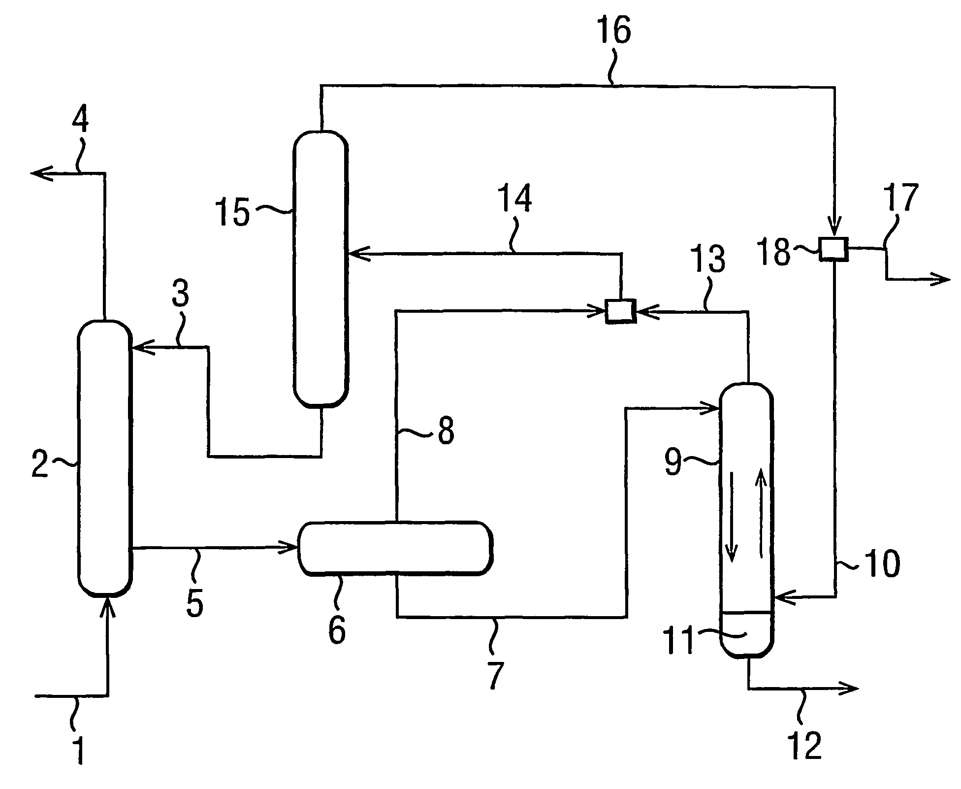
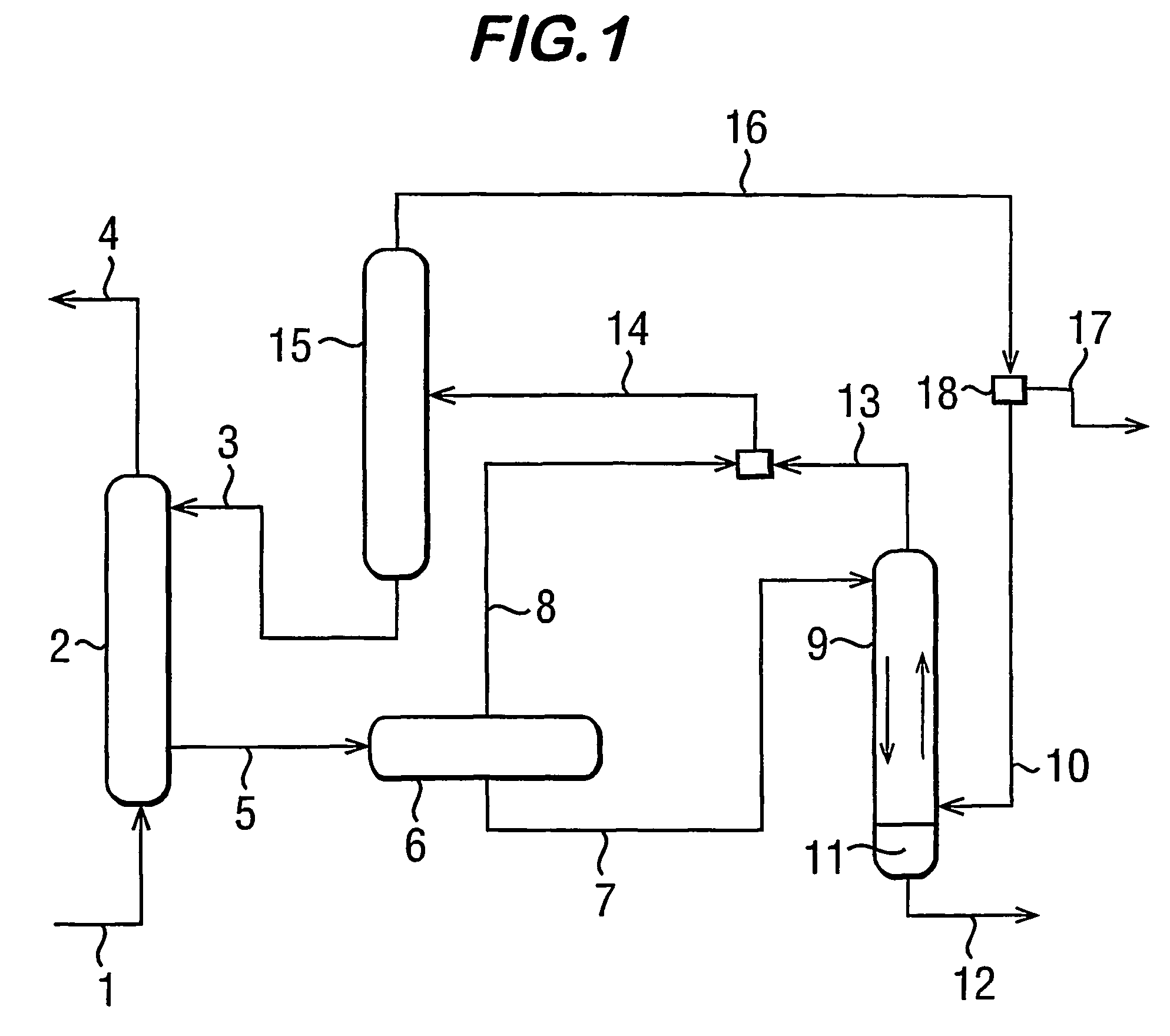
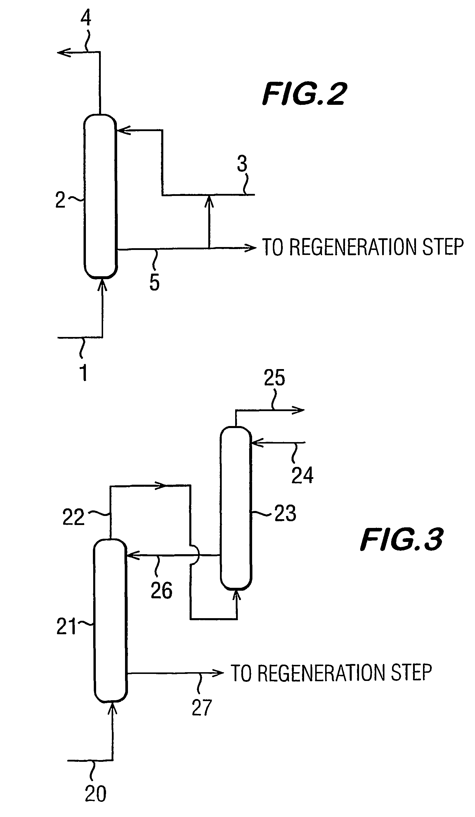
Also, an undesirable side effect of such processes is co-vaporization of arom

Method used


Image

  • Process for dehydrating gas
  • Process for dehydrating gas
  • Process for dehydrating gas

Examples


example 1

[0049]The results given below in Table 1 show the effect of water loading on the cloud point temperature of a mixture of water and N-allyl-dimethylamine.

[0050]

TABLE 1% amine (by% water (byCloud PointAmine (g)Water (g)weight)weight)Temperature (° C.)19109057.92918.281.84839257547.55935.764.347.67943.856.247.810952.647.449.16.390.592.77.3—6.39186.513.5—6.39276.223.859.26.39461.538.550.46.39556.143.949.1

[0051]It can be seen that at water loadings of between 38.5 and 81.8% weight, the cloud point temperature remains relatively constant at approximately 50° C. and that the cloud point temperature increases dramatically at water loadings outside of this range. Accordingly, N-allyl-dimethylamine is suitable for use as a water absorbing fluid in the process of the present invention.

example 2

[0052]The results given below in Table 2 show the effect of water loading on the cloud point temperature of a mixture of water and triethylamine.

[0053]

TABLE 2Cloud Point% amine (by% water (byTemperatureAmine (g)Water (g)weight)weight)(° C.)9.90.1991—9.80.2982659.60.496438.79.50.59552091901018.582802017.473703017.864604017.75550501846406017.237307017.428208017.219109019.60.59.559532.80.49.649639.20.29.8298—0.19.9199—

[0054]It can be seen that at water loadings of between 5 and 90% by weight, the cloud point temperature remains relatively constant at between 17–20° C. and that the cloud point temperature increases dramatically at water loadings outside of this range. Accordingly, triethylamine is highly suitable for use as a water absorbing fluid in the process of the present invention.

example 3

[0055]The results given below in Table 3 show the effect of water loading on the cloud point temperature of a mixture of water and N,N,N′,N′-tetraethyl-1,2-ethanediamine.

[0056]

TABLE 3Cloud Point% amine (by% water (byTemperatureAmine (g)Water (g)weight)weight)(° C.)9.50.5955—91901014.182802025.473703025.864604026.455505026.946406028.237307028.828208031.819109038.90.59.559548.8

[0057]It can be seen that at water loadings of between 20% and 70% weight, the cloud point temperature remains relatively constant at approximately 25 to 29° C. and that the cloud point temperature increases dramatically at water loadings above 70% weight. Accordingly, N,N,N′,N′-tetraethyl-1,2-ethanediamine is suitable for use as a water absorbing fluid in the process of the present invention.


PUM

PropertyMeasurementUnit
Temperatureaaaaaaaaaa

Abstract

A process for the removal of water from gas which comprises an absorption step of bringing a gas saturated with water vapor into gas-liquid contact with a water-lean absorbing liquid comprising a water absorbing liquid having a cloud point temperature above the freezing point of water whereby water vapor present in the gas is absorbed into the water-lean absorbing liquid at a temperature below its cloud point to produce a refined gas having a reduced water vapor content and water-loaded absorbing liquid. A regeneration step is provided in which the water-loaded absorbing liquid is heated to above the cloud point temperature of the absorbing liquid whereby the water-loaded absorbing liquid separates into a water-rich phase and an absorbing liquid-rich phase and the absorbing liquid-rich phase is cooled to a temperature below its cloud point prior to recycling the absorbing liquid-rich phase for use as water-lean absorbing liquid in the absorption step.

Description

[0001]This application is the U.S. national phase of international application PCT / GB02 / 00999, filed 6 Mar. 2002, which designated the U.S.BACKGROUND OF THE INVENTION[0002]This invention relates to a process for dehydrating gas, in particular, natural gas.[0003]Conventional processes for the dehydration of natural gas involve absorption of water into a solvent, such as triethylene glycol. Regeneration of the solvent is achieved by distilling off the absorbed water which requires large amounts of energy. Also, an undesirable side effect of such processes is co-vaporization of aromatics (absorbed from the natural gas) with the water in the distillation step. It is therefore necessary to recover the aromatic compounds before discharging the water to the environment.SUMMARY OF THE INVENTION[0004]The present invention relates to a process for the removal of water from a gas which comprises:[0005](a) an absorption step of bringing a gas saturated with water vapour into gas-liquid contact ...

Claims


Application Information

Patent Timeline
IPC IPC(8): B01D53/28B01D17/00B01D53/14B01D53/26C10L3/10
CPCB01D17/005B01D53/1425B01D53/263C10L3/10B01D17/02B01D17/0202B01D17/0208Y02C10/06Y02C20/40
Inventor COLLINS, IAN RALPHGOODWIN, STEPHEN PAUL
Owner BP EXPLORATION OPERATING CO LTD
Why Eureka
Try Eureka