Liquid repellent member, method for manufacturing liquid repellent member, ink jet head using liquid repellent member, method for manufacturing ink jet head and method for supplying ink

a liquid repellent and member technology, applied in the field of liquid repellent members, can solve the problems of deviation and/or image unevenness, inability to obtain adequate liquid repellency, and loss of fluoride, and achieve the effect of stable and high-quality recording

Inactive Publication Date: 2006-07-11
CANON KK
View PDF26 Cites 4 Cited by
  • Summary
  • Abstract
  • Description
  • Claims
  • Application Information

AI Technical Summary

Benefits of technology

[0025]Accordingly, an object of the present invention is to provide an ink jet head and a method for manufacturing such an ink jet head, in which stable and high quality recording can be achieved by adopting a discharge port constituting member using a liquid repellent member satisfying the above characteristics.

Problems solved by technology

However, when the fluoride is coated, the fluoride is easily peeled by stress in a wiping operation, and, when the fluorine-plasma treatment is used, since the fluoride is merely formed as a surface layer of the discharge port surface having a thickness of about several Å, the fluoride is lost by wear due to stress in the wiping operation or the entire surface of the discharge port surface is not covered by the fluoride to create a surface portion having no fluoride, with the result that adequate liquid repellency cannot be obtained.
In such a contact angle, good ink discharging cannot be achieved, thereby causing deviation and / or image unevenness.
However, since the size of the particle is greater than 0.01 μm and the particles are not dispersed uniformly, in some cases, the discharging direction may become unstable.
In this way, in the conventional orifice plates, adequate liquid repellency and endurance of liquid repellency cannot be obtained.
In this case, when a diameter of the discharge port is about 60 μm, since the mix filler affects little influence upon the shapes of the discharge ports, the ink is discharged without any problem, but, when the diameter of the discharge port is smaller than about 15 μm, since the mix filler affects great influence upon the shapes of the discharge ports, the shapes of the discharge ports are greatly deformed, with the result that a stable image can almost not be obtained.
If the difference is 4 μm, when the ink is discharged onto the entire surface of a recording medium by serial print, positional deviation of 4 μm is generated in every scan, thereby causing density unevenness.
In this way, when a length of discharge port array is increased or arranging density of the discharge ports is increased in order to achieve higher speed and highly fine recording, the positional relationship between the orifice plate and the discharge element substrate is deviated due to the difference in coefficient of thermal expansion, abnormal ink flying may be generated in the vicinity by both ends of the discharge elements or the head may be damaged.
However, as mentioned above, the conventional discharge port constituting members cannot satisfy these characteristics.

Method used


Image

  • Liquid repellent member, method for manufacturing liquid repellent member, ink jet head using liquid repellent member, method for manufacturing ink jet head and method for supplying ink
  • Liquid repellent member, method for manufacturing liquid repellent member, ink jet head using liquid repellent member, method for manufacturing ink jet head and method for supplying ink
  • Liquid repellent member, method for manufacturing liquid repellent member, ink jet head using liquid repellent member, method for manufacturing ink jet head and method for supplying ink

Examples


example 1

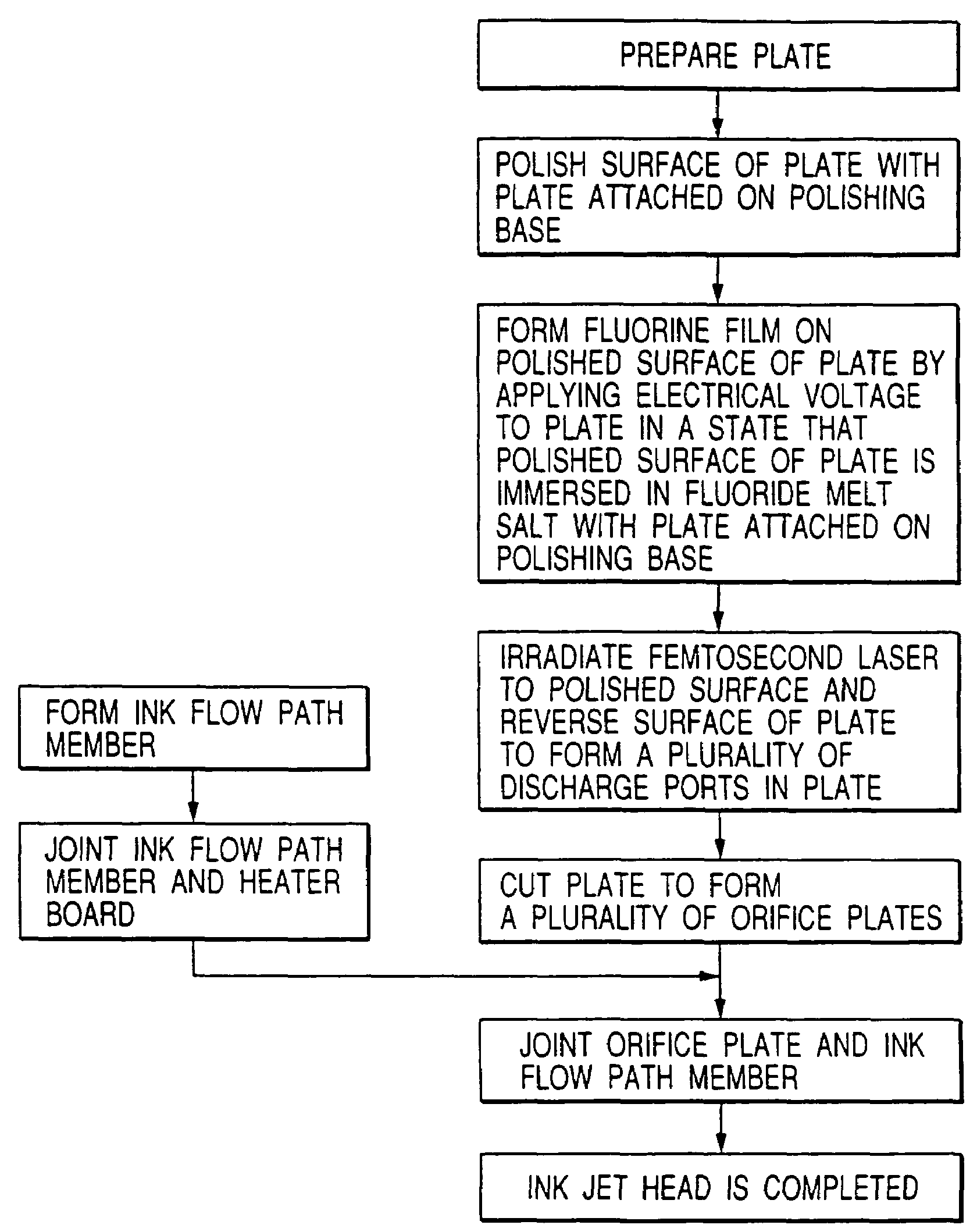
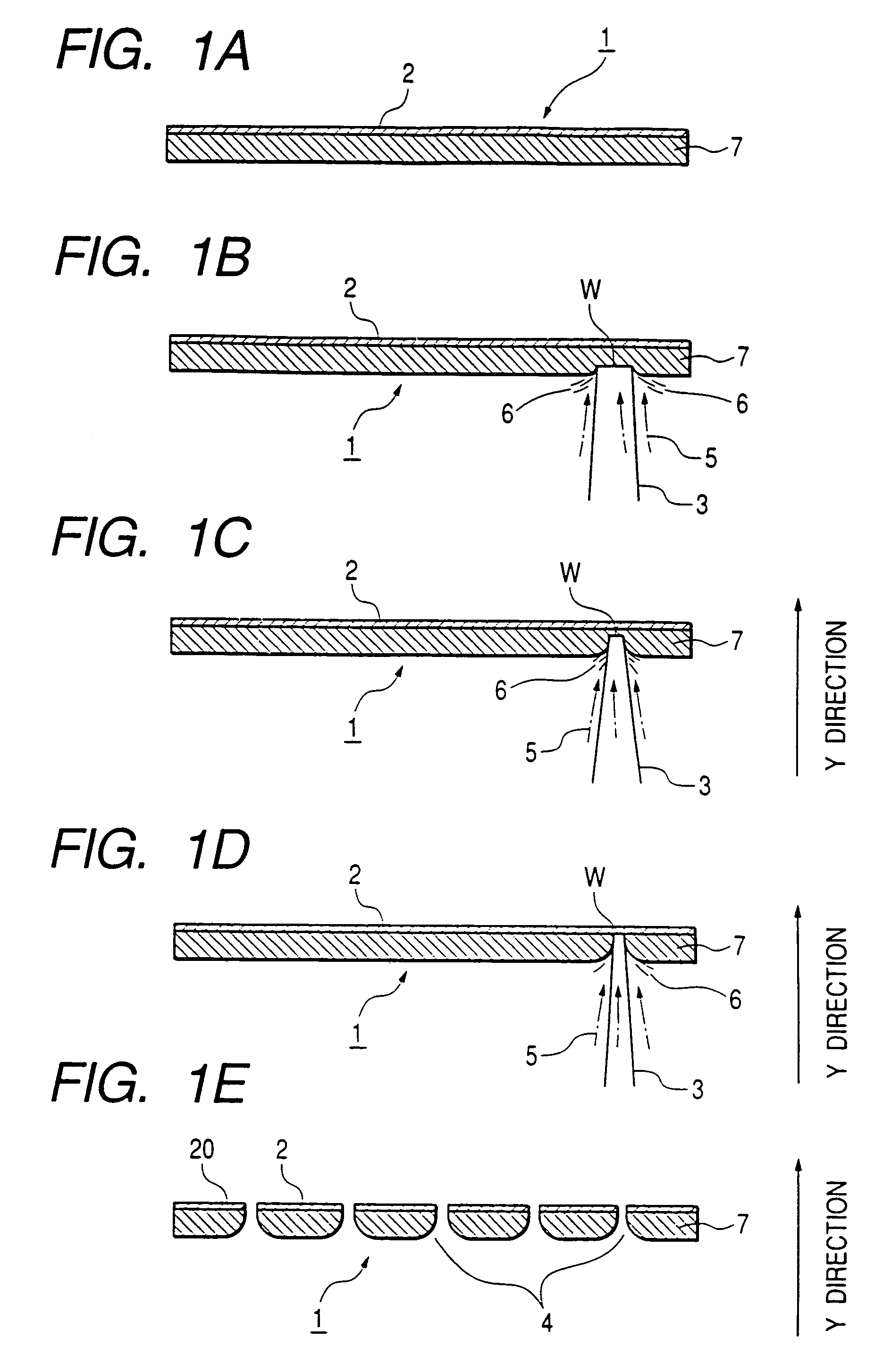
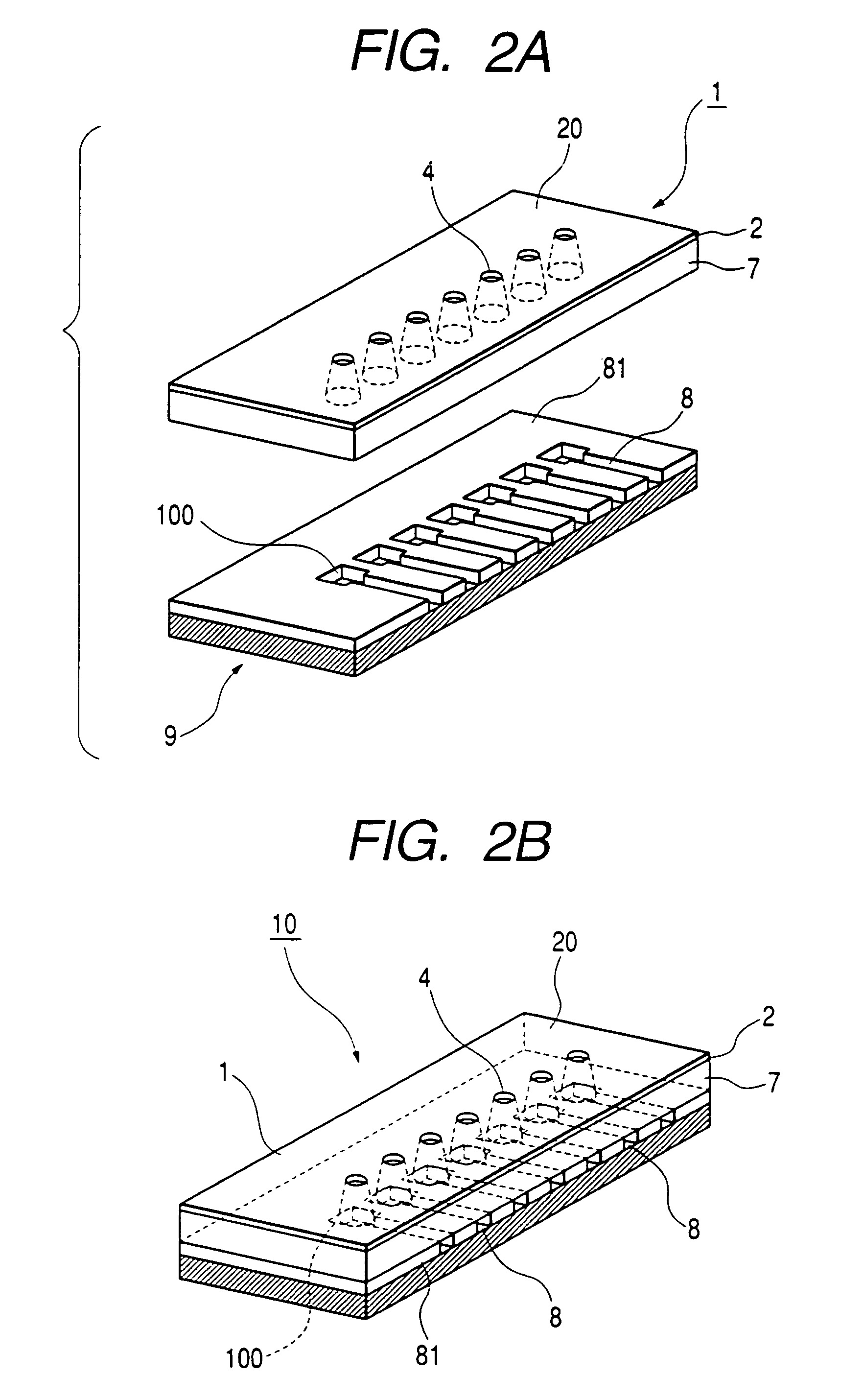
[0099]Now, an example 1 of the present invention will be explained with reference to FIGS. 1A to 1E, FIGS. 2A and 2B and FIG. 4.

[0100]As a crystal carbon constituting member as a member for constituting the orifice plate, c / c composite crystal carbon body manufactured by Nissin Boseki Co., Ltd. (Japan) was used. This is crystal body of carbon which has no internal fine bubbles and is fine and has high bending elastic modulus, Young's modulus and breaking strength and, thus, which is suitable for fine working. Further, in the vicinity of a temperature of 0 to 100° C., coefficient of thermal expansion of the carbon crystal body is about 3.1×10⁻⁶ / ° C. which is the substantially the same as that of silicon. A cylindrical rod stock fired to have a diameter of about 70 mm was cut to obtain a plate material having a thickness of about 0.2 mm, and this plate material was attached to and polished and ground by a polishing machine, thereby obtaining a plate having a thickness of 0.075 mm.

[010...

example 2

[0136]Next, an example 2 of the present invention will be explained with reference to FIG. 11 and FIGS. 12A to 12D.

[0137]First of all, c / c composite crystal carbon body manufactured by Nissin Boseki Co., Ltd. (Japan) was cut to obtain a plate member having a thickness of about 0.2 mm, and both surfaces of the plate member were polished to form a carbon plate having a thickness of 0.135 mm.

[0138]In a condition that the carbon plate 2 is attached to a polishing table, as shown in FIG. 12A, common ink flow paths 80 were formed by a cutting operation. Each common ink flow path 80 had a width of 0.12 mm and a depth of 85 μm.

[0139]Then, by using YAG laser and assist gas, individual ink flow paths 8 each having a depth of about 85 μm were formed in the carbon plate. YAG- 701JH manufactured by Sumitomo Juki Co., Ltd. (Japan) was used to the YAG laser, and illumination energy was selected to 0.1 to 16 J / pulse and a pulse time was selected to 0.8 to 8 msec. As an optimum condition, it was fou...


PUM

PropertyMeasurementUnit
contact angleaaaaaaaaaa
sizeaaaaaaaaaa
diameteraaaaaaaaaa

Abstract

The present invention provides a liquid repellent member applied to ink jet, comprising a carbon substrate, and a liquid repellent film formed on a surface of the carbon substrate and formed by bonding between carbon and fluorine.

Description

[0001]This is a divisional application of application Ser. No. 10 / 067,220, filed on Feb. 7, 2002, now U.S. Pat. No. 6,685,301.BACKGROUND OF THE INVENTION[0002]1. Field of the Invention[0003]The present invention relates to a liquid repellent member, a method for manufacturing such a liquid repellent member, an ink jet head using such a liquid repellent member, a method for manufacturing such an ink jet head, and a method for supplying ink.[0004]2. Description of the Related Art[0005]In the past, a liquid repellent member having a surface for increasing a contact angle with respect to liquid has been used as various applications for various purposes. For example, the liquid repellent member is used in an ink jet head. In some ink jet heads, a discharge port constituting member for defining a plurality of discharge ports for discharging ink has a discharge port surface in which the plurality of discharge ports are formed, and such a discharge port surface is constituted by a liquid re...

Claims


Application Information

Patent Timeline
Patent Type & Authority Patents(United States)
IPC IPC(8): C25D3/66B41J2/175B23K26/18B41J2/135B41J2/14B41J2/16
CPCB23K26/0635B23K26/4095B23K26/388B41J2/1606B41J2/162B41J2/1623B41J2/1632B41J2/1634B23K26/4005B23K26/401B23K26/4065B23K26/4075B23K26/408B23K26/4085B23K26/18B23K26/0624B23K26/40B23K26/389B23K2101/34B23K2101/35B23K2103/05B23K2103/26B23K2103/42B23K2103/50B23K2103/52
Inventor EIDA, MASATAKAIWATA, KAZUOHASEGAWA, TOSHINORI
Owner CANON KK
Why Eureka
Try Eureka