
Osmotic delivery system with early zero order push power engine

a technology of push power and osmotic agent, which is applied in the direction of inorganic non-active ingredients, prosthesis, oil/fat/waxes non-active ingredients, etc., can solve the problems of inability to meet the needs of osmotic agent expansion, inability to meet the needs of osmotic composition tableted, and inability to meet the needs of osmotic composition, etc., to achieve the effect of less variable engine performan

Inactive Publication Date: 2006-07-11
INTARCIA THERAPEUTICS INC
View PDF16 Cites 105 Cited by
  • Summary
  • Abstract
  • Description
  • Claims
  • Application Information

AI Technical Summary

Benefits of technology

[0010]The present invention relates to an osmotic engine that reaches zero order push power relatively quickly after being placed in a fluid environment of use. The present invention also relates to the manufacture of osmotic engines with rapid achievement of zero order push power and to the manufacture of osmotic delivery systems containing such engines. The present invention also relates to an osmotic delivery system whose osmotic engine reaches zero order push power soon after being placed in a fluid environment of use. In other words, the startup time for a three-month delivery system is less than 10% of the anticipated life of the osmotic delivery system. This startup time is achieved by including in the system an osmotic engine that comprises a viscous, flowable composition. The osmotic agent composition is preferably prepared by mixing an osmotic agent and a fluid vehicle to result in a viscous, flowable composition in which the osmotic agent is evenly distributed. The preferred osmotic agent composition can then be loaded into the osmotic delivery system in a one-step process. Since the composition is flowable rather than dry, less air is entrapped. Furthermore, the flowable composition may be de-aerated prior to being loaded into the system in order to remove any residual entrapped air. As a result, the osmotic engine starts up quickly and reaches a zero order push rate early, and engine performance is much less variable from system to system.

Problems solved by technology

When the system is placed in a fluid environment, water is imbibed from the environment into the system by the osmotic agent, resulting in expansion of the osmotic agent.
However, there are potential disadvantages to this kind of engine.
For instance, an osmotic delivery system that includes an osmotic engine comprising a tableted osmotic composition may require a startup time that is undesirably long.
The compressibility of the tableted composition results in a delay in startup as the entrapped air is compressed and causes the osmotic engine to expand at a rate that is less than proportional to the volume of water imbibed through the semipermeable membrane, at least until startup is achieved.
If too much air is entrapped during the manufacture of the tableted osmotic engine or during assembly of the osmotic delivery system, the startup time of the system may be undesirably high for a desired application.
Another potential disadvantage of an osmotic delivery device that includes an osmotic engine formed using a tableted osmotic composition is that such an osmotic engine requires at least one manufacturing step that may be avoided.
In some instances, excess filler may overflow the engine compartment.

Method used


Image

  • Osmotic delivery system with early zero order push power engine
  • Osmotic delivery system with early zero order push power engine
  • Osmotic delivery system with early zero order push power engine

Examples


example 1

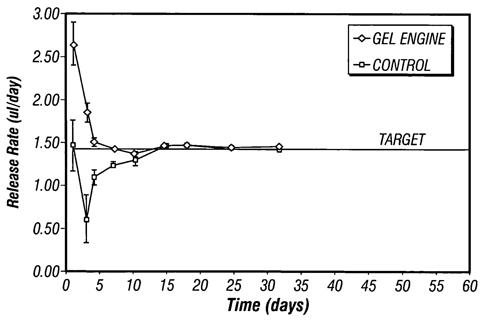
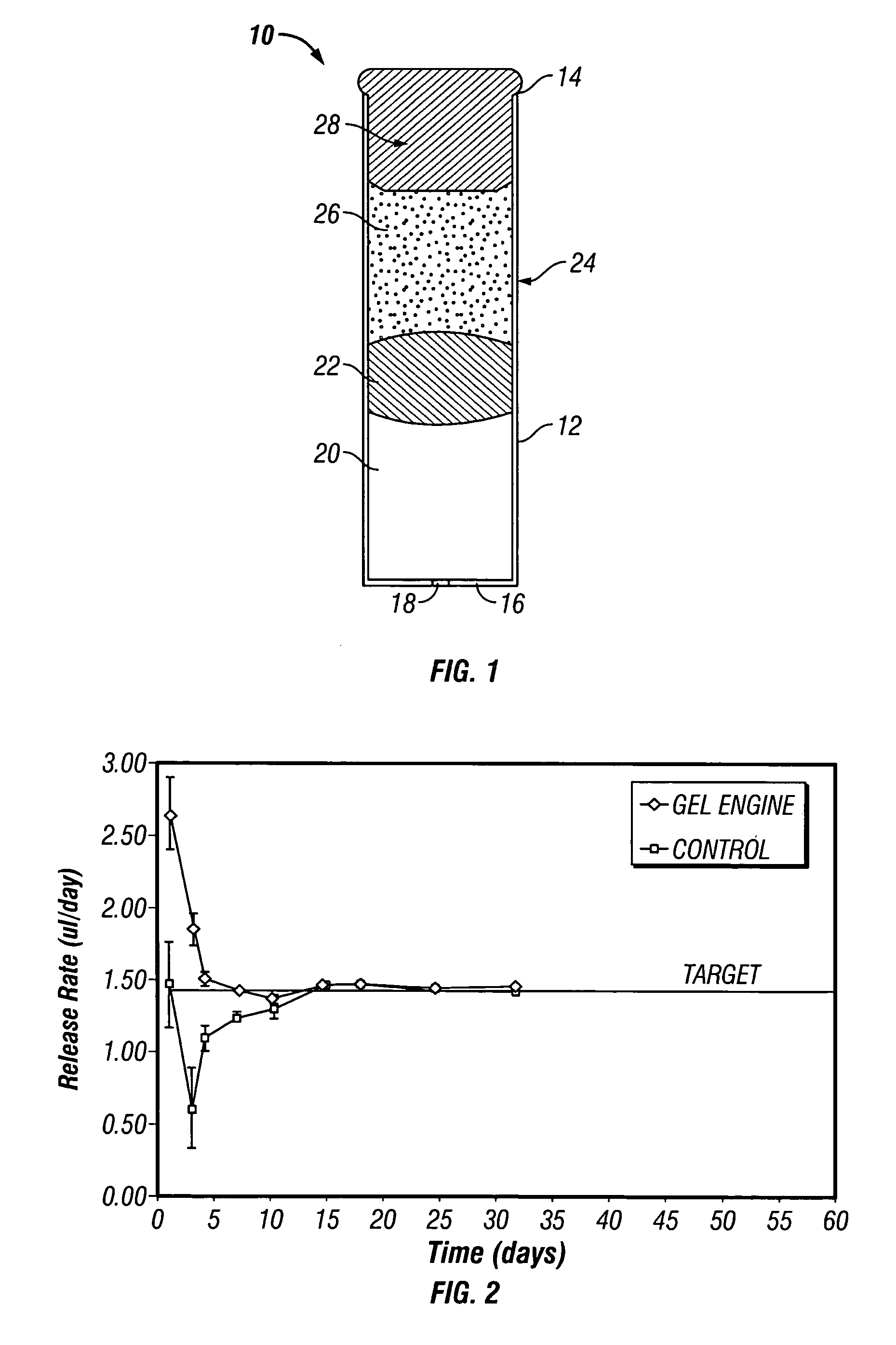
[0091]A fluid vehicle of a polyvinylpyrrolidone (pvp, MW 12,000):polyethylene glycol 400 (PEG 400) formulation (40:60) was mixed with NaCl to manufacture a 60-day engine. 30% (w / w) of the fluid vehicle and 70% (w / w) of NaCl were blended together under vacuum until a homogeneous suspension was formed. The suspension was loaded into a syringe. To assemble an osmotic delivery system, a cylindrical titanium reservoir was loaded with a plunger-type piston that created two compartments: the osmotic engine compartment and the beneficial agent compartment. The suspension engine composition was inserted into the entire osmotic engine compartment using a syringe and a needle. The engine end of the reservoir was then capped with a semipermeable membrane. The control system contained two NaCl tablets and a PEG 400 filler in the engine compartment. Blue dye was used in the place of the beneficial agent to assess the release rate.

[0092]To test the performance of the system, the osmotic system was...

example 2

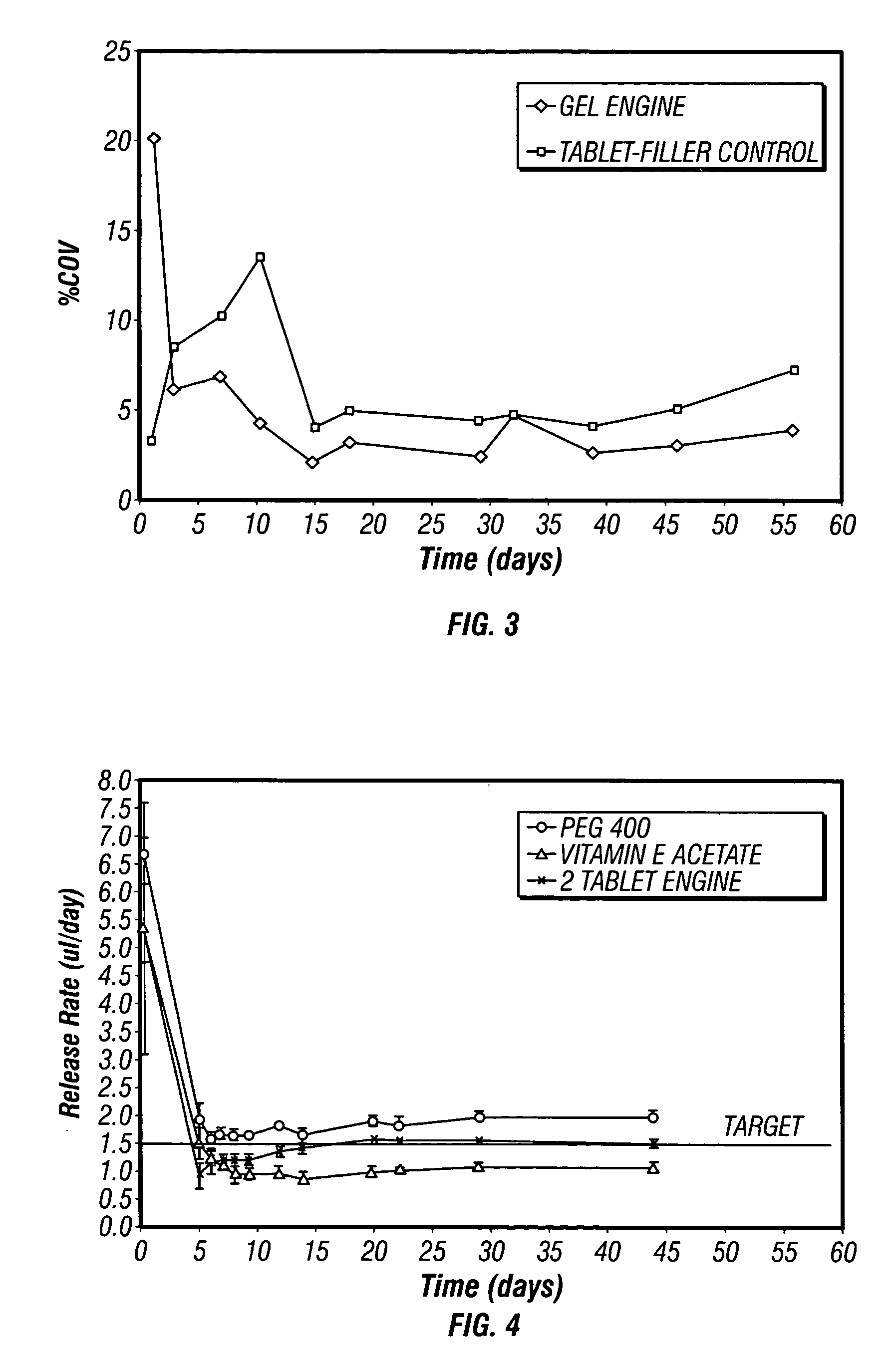
[0094]Fluid vehicles with limited osmotic power and low infiltration activity in the semipermeable membrane were used to make flowable engines with sodium chloride. A fluid vehicle with limited osmotic power is beneficial because if the fluid vehicle has osmotic power, this additional osmotic power will complicate the osmotic power of the osmotic agent, and the performance of the osmotic system may deviate from the predicted one. Similarly, a fluid vehicle that infiltrates the semipermeable membrane will cause the membrane to swell and may alter the imbibition rate by increasing or decreasing the rate at which water passes through the membrane. As a result, varying delivery rates are observed for an extended period of time before stabilization.

[0095]Table 1 shows the weight gain of membranes over time at 37° C. using soybean oil, glycerol, polysorbate 60, vitamin E acetate, or PEG 300 as a fluid vehicle in a flowable engine according to the present application. The control engine co...

example 3

[0098]To determine if the present invention is applicable to delivery systems of various delivery durations, systems with a 45-, 90-, or 180-day delivery duration were tested and the results are summarized in Table 2. The flowable engine contained sodium chloride and polysorbate 80 prepared according to the present invention, whereas the control engine contained two sodium chloride tablets and the PEG 400 filler.

[0099]

TABLE 2Percent Startup to Total Delivery DurationDelivery DurationStartup Time% Startup to(days)(days)Delivery DurationFlowable engine4536.79044.418084.4Control Engine901213.3

[0100]These results show that the flowable engine significantly reduced the startup time of systems of every duration tested, and the effect is more profound when the delivery duration is longer.


PUM

PropertyMeasurementUnit
Fractionaaaaaaaaaa
Fractionaaaaaaaaaa
Fractionaaaaaaaaaa

Abstract

The present invention is directed to an osmotic engine useful in an osmotic delivery system for delivery of a beneficial agent in a controlled manner over a preselected administration period. By including a flowable engine comprising at least one osmotic agent and at least one fluid vehicle, the resulting osmotic engine reaches a zero order push power or push rate quickly and provides steady delivery of the beneficial agent.

Description

FIELD OF THE INVENTION[0001]This present invention is directed to an osmotic engine useful in an osmotic delivery system for delivery of a beneficial agent in a controlled manner over a preselected administration period, to osmotic delivery systems containing the osmotic engine, and to methods for preparing both the osmotic engine and the osmotic delivery system.BACKGROUND OF THE INVENTION[0002]It has been a goal in the drug delivery field to treat a disease by prolonged delivery of a beneficial agent, such as a drug, at a controlled rate. Various approaches have been taken toward this end. For example, implantable diffusional systems have been used to deliver a drug that is released by simple diffusion. In another approach, osmotic delivery systems have been used to provide more accurately controlled delivery than simple diffusion. The osmotic delivery systems can be implanted into a living organism to release the beneficial agent in a controlled manner over a preselected administr...

Claims


Application Information

Patent Timeline
IPC IPC(8): A61F2/00A61K9/10A61K9/00A61K9/22A61K9/48A61K47/02A61K47/30A61K47/34A61K47/44A61K47/46
CPCA61K9/0004A61K9/4808A61K9/0024A61K9/00A61K9/20A61K9/48
Inventor FEREIRA, PAMELA J.BERRY, STEPHEN A.
Owner INTARCIA THERAPEUTICS INC
Features
  • Generate Ideas
  • Intellectual Property
  • Life Sciences
  • Materials
  • Tech Scout
  • Unparalleled Data Quality
  • Higher Quality Content
  • 60% Fewer Hallucinations
Learn More