Synchronous pipeline with normally transparent pipeline stages

a pipeline stage and pipeline technology, applied in the direction of generating/distributing signals, liquid/fluent solid measurement, instruments, etc., can solve the problems of chip power consumption, chip and system level cooling and packaging costs have increased, etc., to minimize synchronous design power and increase clock gating flexibility. , the effect of reducing pipeline operating frequency

Active Publication Date: 2006-07-11
IBM CORP
View PDF2 Cites 43 Cited by
  • Summary
  • Abstract
  • Description
  • Claims
  • Application Information

AI Technical Summary

Benefits of technology

[0012]It is another purpose of the invention to increase clock gating flexibility;
[0013]It is yet another purpose of the invention to minimize synchronous design power without reducing pipeline operating frequency.

Problems solved by technology

Thus, not withstanding the decrease of chip supply voltage, chip power consumption has increased as well.
Chip and system level cooling and packaging costs have escalated as a natural result of this increase in chip power.

Method used


Image

  • Synchronous pipeline with normally transparent pipeline stages
  • Synchronous pipeline with normally transparent pipeline stages
  • Synchronous pipeline with normally transparent pipeline stages

Examples


Embodiment Construction

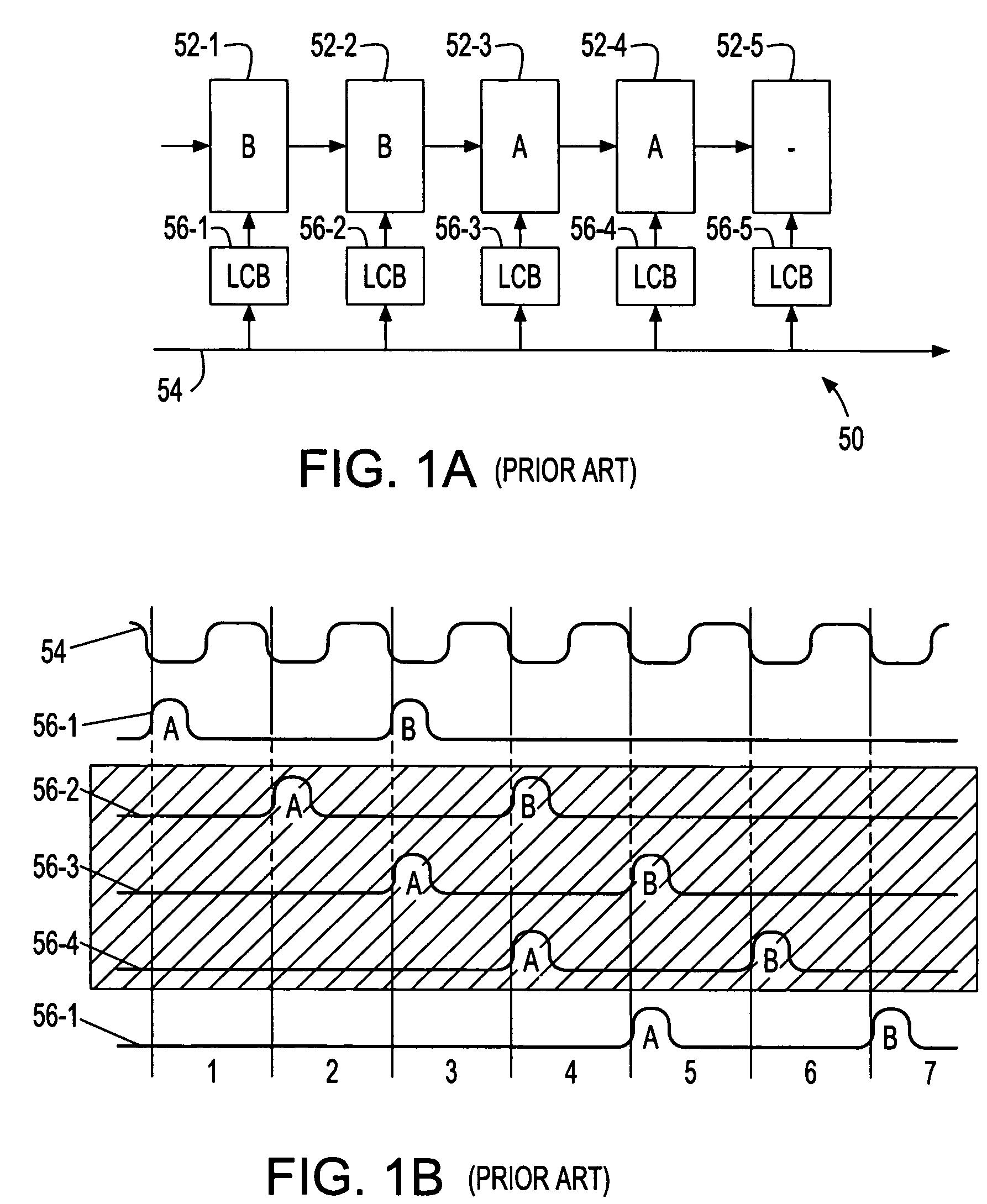
[0025]Turning now to the drawings and, more particularly, FIGS. 1A–B show data propagating through an example of a typical prior art N by M pipeline register cross section 50 with a corresponding timing diagram. In this example N is five pipeline stages 52-1, 52-2, 52-3, 52-4, 52-5 that are normally opaque by default and, M may be any register width suitable for the particular application. A global clock 54 provides a timing edge from which local clocks 56-1, 56-2, 56-3, 56-4, 56-5 are generated for each pipeline stage 52-1, 52-2, 52-3, 52-4, 52-5. Each stage 52-1, 52-2, 52-3, 52-4, 52-5 is clocked (pulsed transparent) to allow local data items to propagate through and be latched in the (subsequently opaque) stage 52-1, 52-2, 52-3, 52-4, 52-5. Data items propagate through the pipeline 50 clocked by a local clock pulse 56-1, 56-2, 56-3, 56-4, 56-5 that temporarily pulses the respective stage 52-1, 52-2, 52-3, 52-4, 52-5 transparent. After sufficient time for the data item to pass thr...


PUM


Abstract

A synchronous pipeline segment and an integrated circuit (IC) including the segment. The segment includes an input stage, an output stage and at least one intermediate stage. A place holder latch associated with each stage indicates whether valid stage data is in the stage. A local clock buffer provides a local clock gating a corresponding stage. The input and output stages are normally opaque and intermediate stages are normally transparent. Data items pass locally asynchronously between the input and output stages and are separated by opaque gated intermediate stages.

Description

CROSS REFERENCE TO RELATED APPLICATION[0001]The present invention is related to U.S. application Ser. No. 10 / 262,769 entitled “INTERLOCKED SYNCHRONOUS PIPELINE CLOCK GATING” to Hans M. Jacobson et al., filed Oct. 2, 2002, and assigned to the assignee of the present invention.BACKGROUND OF THE INVENTION[0002]1. Field of the Invention[0003]The present invention generally relates to synchronous integrated circuits and more particularly to reducing power consumption in a synchronous pipeline circuit.[0004]2. Background Description[0005]Semiconductor technology and chip manufacturing advances have resulted in a steady increase of on-chip clock frequencies, the number of transistors on a single chip and the die size itself accompanied by a corresponding decrease in chip supply voltage. Generally, the power consumed by a given clocked unit (e.g., latch, register, register file, functional unit and etc.) increases linearly with the frequency of switching within the unit. Thus, not withstand...

Claims


Application Information

Patent Timeline
Patent Type & Authority Patents(United States)
IPC IPC(8): G06F1/04G06F1/10G06F1/12G06F1/26G06F9/38
CPCG06F1/10G06F9/3869G06F5/08
Inventor JACOBSON, HANS M.
Owner IBM CORP
Why Eureka
Try Eureka