Device for the comminution of materials

a technology of loosely packed materials and compacting devices, which is applied in the direction of application, grain husking, grain treatment, etc., can solve the problems of affecting the conveying effect of synthetic materials, so as to facilitate the replacement of parts and facilitate the maintenance of the device, the effect of facilitating the maintenan

Inactive Publication Date: 2006-07-18
STARLINGER & CO GMBH
View PDF18 Cites 7 Cited by
  • Summary
  • Abstract
  • Description
  • Claims
  • Application Information

AI Technical Summary

Benefits of technology

[0012]By said solution according to the invention of arranging bearings, in-particular the bearing opposite the drive, on the inside of the shredder / conveyor rotor body, it is no longer necessary to cut back on the rigidity of the bearing, and wear of the feed area of the extruder will be reduced substantially. Moreover, the transfer area between the shredder / conveyor rotor body and the extruder screw is free of webs or supports which would impede the material transport. Furthermore, the shredder / conveyor rotor body can be liquid-cooled on its inside.
[0014]The maintenance of the device is rendered particularly easy and the replacement of parts is facilitated if the abutment body is introducible from the outside of the casing through an opening in the casing into the hollow space of the shredder / conveyor rotor body. A spacesaving design and easy maintenance can be achieved by means of an embodiment wherein the abutment body is a hollow body open at both ends, through the interior of which a drive shaft of the extruder screw passes. This design also renders it possible to position the drive shaft of the extruder screw in the interior of the abutment body.
[0015]The invention provides various possibilities of driving the shredder / conveyor rotor body and the extruder screw. Thus, the shredder / conveyor rotor body and the extruder screw can be driven via a common drive motor, whereby facultatively separate transmissions may be provided for achieving different rotational speeds. Alternatively, the shredder / conveyor rotor body and the extruder screw may possess separate drives, providing extensive possibilities of control.

Problems solved by technology

In said device, the discharge-end bearing of the cutting shaft has a negative impact on the conveying effect of the synthetic material.
The webs provided for supporting the discharge-end bearing represent a substantial obstacle to the material transport and may lead to a considerable curtailment of the material flow, in particular in case of lightweight and fibrous materials.
Furthermore, the maintenance of the bearing is difficult and its replacement, respectively, is hardly possible, since such can only be accomplished if the associated installations have been dismantled completely and / or the cutting shaft has been removed.
Moreover, the bearing is exposed to an increased temperature load because of its assembly position, in particular if the associated screw is an extruder screw.
However, said solution exhibits a disadvantage in that the cutting forces that occur lead to a very substantial radial strain on the extruder screw and hence to increased wear, in particular if the feed opening of the extruder screw is enlarged by pocket-like expansions which, on the one hand, increase the delivery rate of the extruder but, on the other hand, result in even more increased wear as the screw rests on the webs at selective points.
Moreover, the drive-end bearing of the cutting shaft is expensive and can, in a fully functional machine, only be configured as a widely projecting portion.
This, in turn, creates an increased thermal load of the material caused by milling and can even result in the melting of the material, in particular in case of thermally sensitive materials such as an LLDPE stretch film.
One disadvantage of that design is that the material is pressed directly in the direction of the bearing by a compression of the feed screw and hence the sealing of the bearing against dust and impurities will involve substantial expenses and, furthermore, the deflection of the material toward the extruder will cause an additional thermal load of the material, thus leading to increased degradation values.
If in said device an extruder screw was directly connected to the feed screw, the same disadvantages as described above would occur.
However, said extruder does not exhibit a separate abutment body for the rear screw part.
All above-mentioned devices have a common disadvantage in that increased deflection forces occur because of the material transfer from the knife-supporting shredding device to the feed or extruder screw, which deflection forces are oriented normally to the centre line of the consecutively arranged shredding and extruder shafts, thus leading to increased wear in the feed area of the extruder or feed screw if an additional discharge-end bearing is omitted, and / or in that the known embodiments of discharge-end bearings lead to substantial curtailments of the material transport or to an increased thermal load of the material.

Method used


Image

  • Device for the comminution of materials
  • Device for the comminution of materials
  • Device for the comminution of materials

Examples


Embodiment Construction

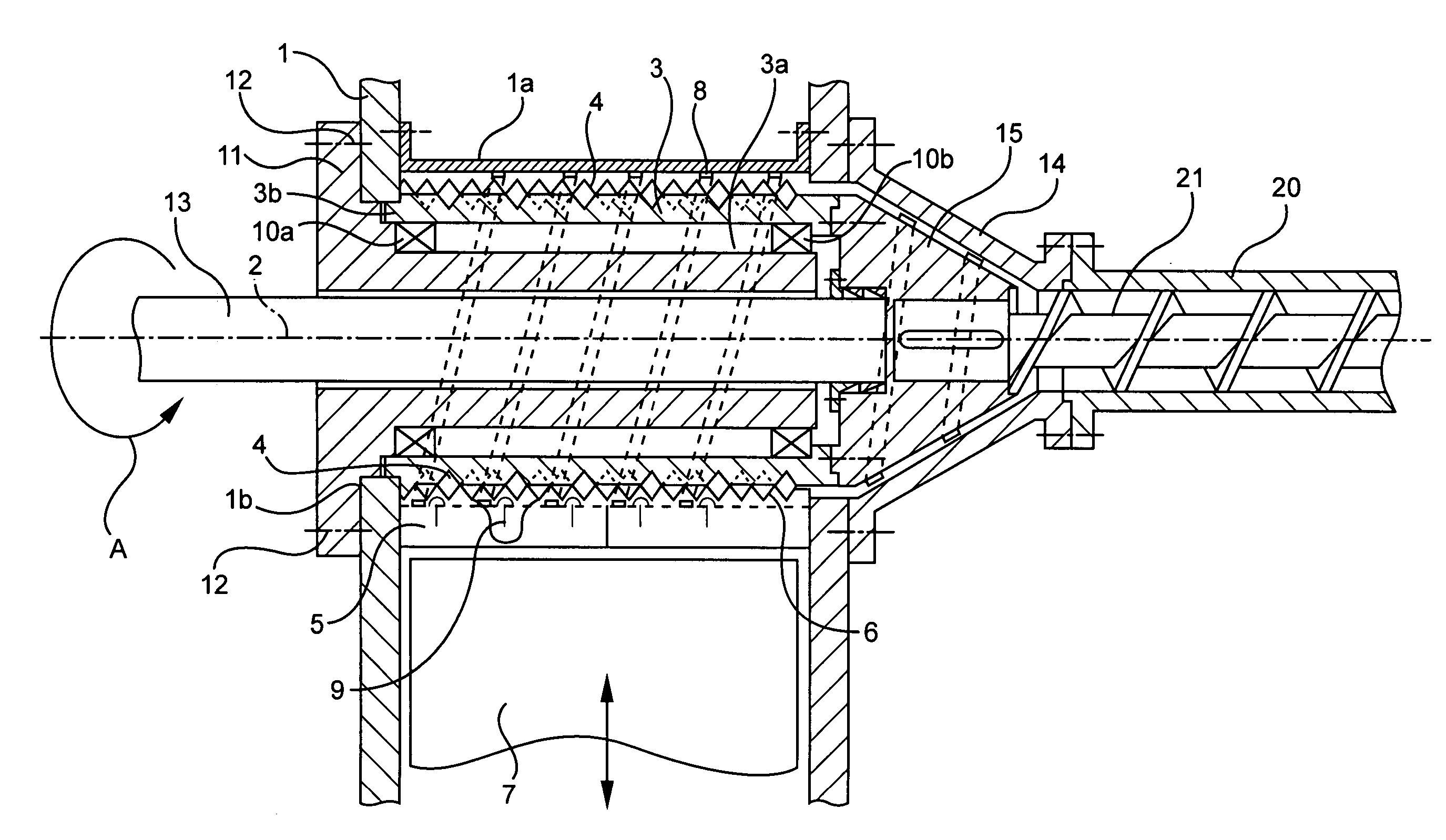
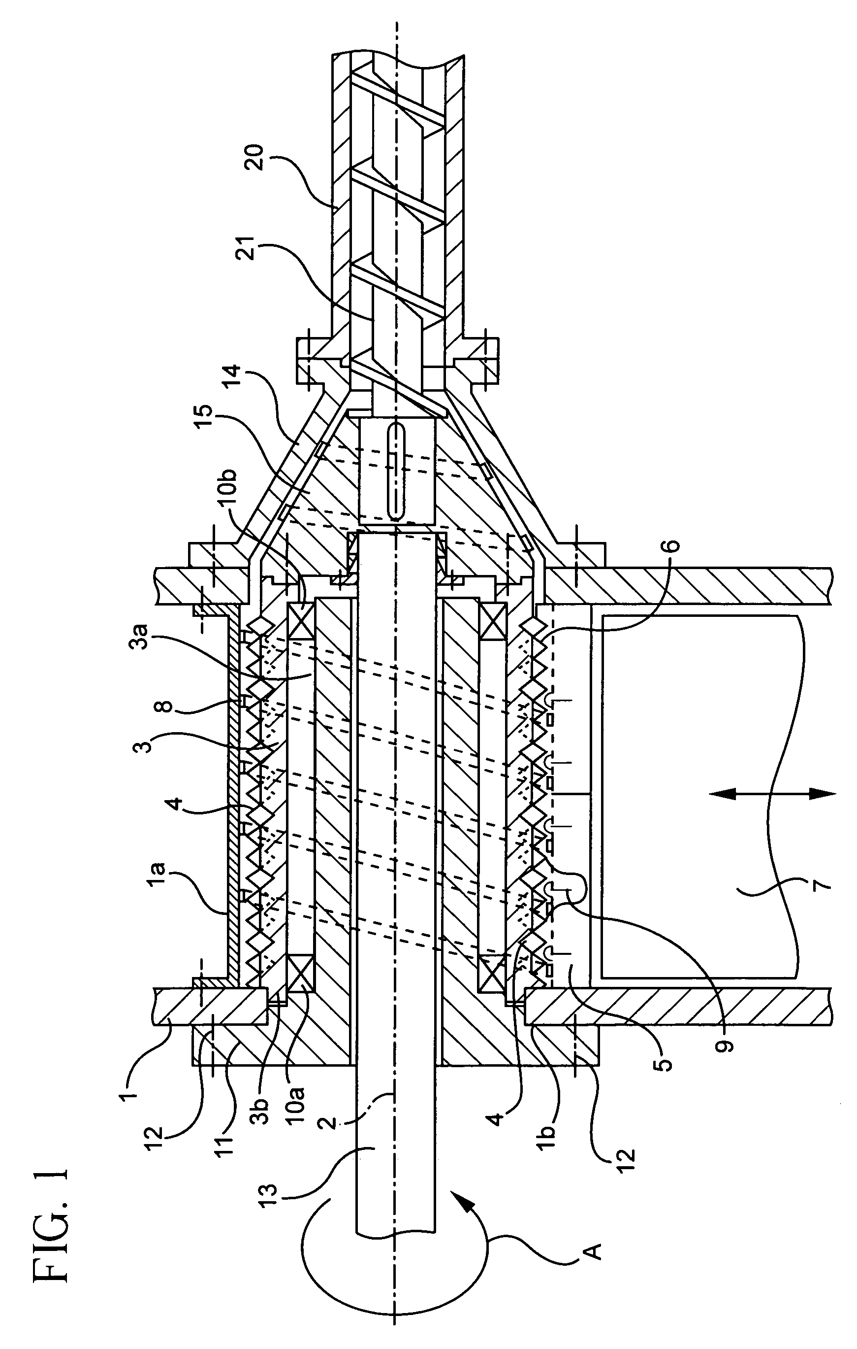
[0027]First with reference to FIG. 1, there is illustrated, in longitudinal section, a first embodiment of the device according to the invention for compacting loosely packed materials, in particular synthetic materials. Said device comprises a casing 1, 1a, in which a shredder / conveyor rotor body configured as a shredder shaft 3 is rotatably arranged around an axis of rotation 2 (arrow A). The shredder shaft 3 has a plurality of mutually offset knives 4 at its peripheral surface, which may be arranged helically around the periphery. Opposite to the rotating knives 4 there are stationary knives 5 extending inwardly from the casing 1a so that between the knives 4 and 5 narrow shear gaps 6 are formed.

[0028]In a manner which is known and therefore not illustrated, material to be shredded is supplied to the shredder shaft 3 via a feeding hopper, using suitable conveyor means such as conveyor belts, a roll feeder, a lifting and tipping device or by manual charging. The material can there...


PUM

PropertyMeasurementUnit
angleaaaaaaaaaa
current consumptionaaaaaaaaaa
temperatureaaaaaaaaaa

Abstract

A device for compacting loosely packed materials, in particular synthetic materials, comprises a shredder / conveyor rotor body arranged in a casing and drivable with the rotation around an axis of rotation and a consecutively arranged extruder with an extruder screw that is arranged rotatably and coaxially to the shredder / conveyor rotor body. Materials supplied to the shredder / conveyor rotor body are conveyed to the extruder screw, whereby they optionally are shredded. According to the invention, the shredder / conveyor rotor body is configured as a hollow body open at the front side opposite the extruder and has at least one rotary bearing in its interior, which rotary bearing rests on an abutment body projecting from the open front side into the interior of the shredder / conveyor rotor body.

Description

CROSS-REFERENCE TO RELATED APPLICATIONS[0001]This application is a continuation of International Patent Application No. PCT / AT03 / 00069 with a filing date of Mar. 11, 2003. This application claims priority to Austrian Application Serial No. A 376 / 2002 with a filing date of Mar. 12, 2002.BACKGROUND OF THE INVENTION[0002]The invention relates to a device for compacting loosely packed materials, in particular synthetic materials, comprising a shredder / conveyor rotor body arranged in a casing and rotatably drivable around an axis of rotation and a consecutively arranged extruder with an extruder screw that is arranged rotatably and coaxially to the shredder / conveyor rotor body so that materials supplied to the shredder / conveyor rotor body are conveyed to the extruder screw, whereby they optionally are shredded.[0003]The material to be compacted, usually synthetic material, is supplied into a feeding hopper via suitable conveyor means such as a conveyor belt, a roll feeder, a lifting and ...

Claims


Application Information

Patent Timeline
Patent Type & Authority Patents(United States)
IPC IPC(8): B02C19/22B02C18/14B02C18/22B02C18/24B29B17/00B29B17/04B29C48/03B29C48/50
CPCB02C18/141B02C18/145B02C18/146B02C18/2216B02C18/24B29B17/0412B29B17/0042B29C47/585B29B2017/046B29B2017/0476B29C47/0009B29C47/0801Y02W30/62B29C48/03B29C48/252B29C48/501Y02W30/52
Inventor STARLINGER-HUEMER, ERNAHUEMER, ANGELIKAFELLINGER, MARKUS
Owner STARLINGER & CO GMBH
Why Eureka
Try Eureka