Turbomachine

a technology of turbines and motors, applied in the field of turbines, can solve the problems of reducing bearing friction and running accuracy of turborotors, and achieve the effects of increasing the thermal protection of shaft bearings, increasing the protective effect, and cost-effective bearing suppor

Active Publication Date: 2006-07-18
ATLAS COPCO ENERGAS
View PDF1 Cites 7 Cited by
  • Summary
  • Abstract
  • Description
  • Claims
  • Application Information

AI Technical Summary

Benefits of technology

[0009]Preferably, the bearing housing has shaft ducts for the shaft of the turborotor, which are provided with heat insulation, in order to further increase the thermal protection of the shaft bearings. In addition, the shaft segments between the bearing housing and the rotor disk, i.e. the rotor, ca

Problems solved by technology

In total, the encapsulation of the shaft bearings in the common bearing housing further i

Method used


Image

  • Turbomachine
  • Turbomachine

Examples


Embodiment Construction

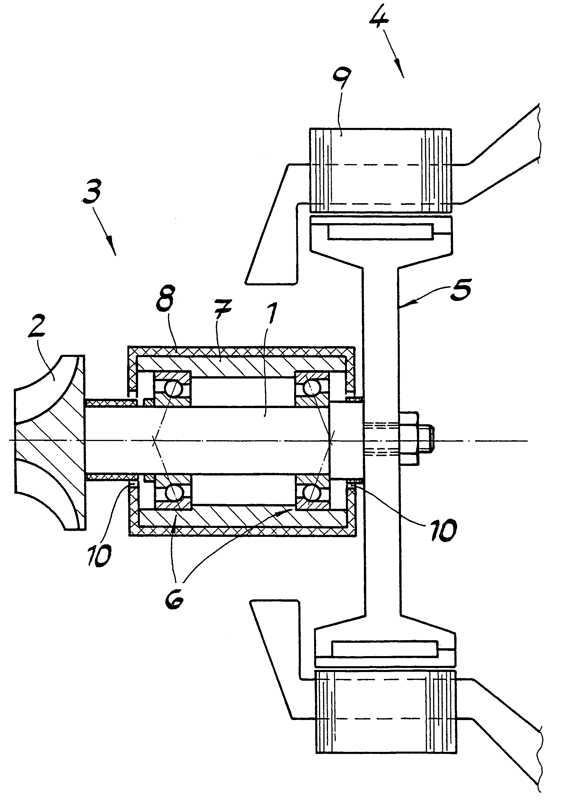
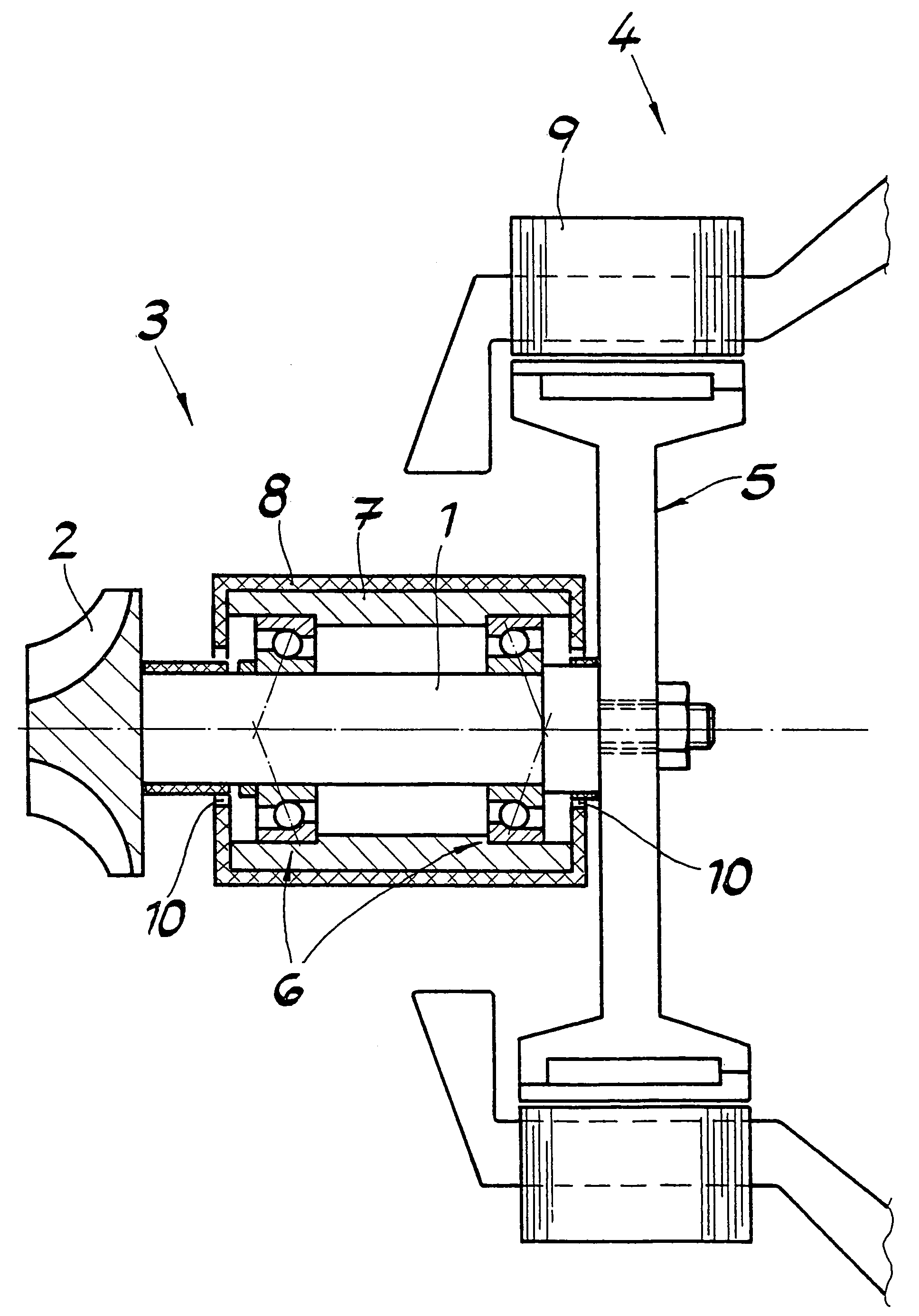
[0013]The turbomachine shown in the sole FIGURE has a turborotor 3 made up of a shaft 1 and a rotor disk 2, and an electric machine 4 only shown partially, having an electric rotor 5 and a stator 9. Rotor disk 2 is arranged on one end of shaft 1, in overhung manner. Electric rotor 5 is connected with shaft 1 of turborotor 3 and also arranged in overhung manner on the other end of shaft 1.

[0014]Shaft 1 is mounted in shaft bearings 6 in a bearing housing 7. Housing 7 thermally separates shaft bearings 6 from electric machine 4 and is preferably provided with insulation 8. Shaft bearings 6, together with bearing housing 7, form a sealed unit. The bearing holder surfaces of bearing housing 7 can therefore be produced in a single chucking process. This arrangement allows a high level of production accuracy and, at the same time, low expenditure. A very high level of alignment accuracy of shaft bearings 6 relative to one another can be guaranteed. Turborotor 3 is therefore characterized b...


PUM


Abstract

A turbomachine has a turborotor made up of a shaft and a rotor disk, and an electric machine having an electric rotor. The rotor disk is arranged at one end of the shaft, in overhung manner, and the electric rotor is connected with the shaft of the turborotor. The electric rotor is arranged on the other end of the shaft, also in overhung manner, and the shaft is mounted on shaft bearings in a bearing housing that thermally separates the shaft bearings from the electric machine.

Description

CROSS REFERENCE TO RELATED APPLICATIONS[0001]Applicant claims priority under 35 U.S.C. §119 of German Application No. 103 10 677.4 filed Mar. 12, 2003.BACKGROUND OF THE INVENTION[0002]1. Field of the Invention[0003]The present invention relates to a turbomachine having a turborotor made up of a shaft and a rotor disk, and an electric machine having an electric rotor, whereby the rotor disk is arranged at one end of the shaft, in overhung manner, and whereby the electric rotor is connected with the shaft of the turborotor.[0004]2. The Prior Art[0005]In the case of the turbomachines known from practice, having the characteristics described initially, the shaft is mounted on both sides of the electric rotor. This turborotor configuration makes great demands on the required production precision of the bearing holder bores. These demands particularly become significant when using fast-running high-precision roller bearings, which demand an alignment accuracy of the bearings relative to o...

Claims


Application Information

Patent Timeline
IPC IPC(8): F01D25/16F04D29/04F04D29/056F04D29/059F04D29/28F04D29/58H02K5/08H02K5/173H02K7/14H02K7/18H02K9/00
CPCF04D29/059F04D29/5853H02K7/14H02K7/1823H02K5/1735H02K5/08H02K9/00H02K11/0094
Inventor BOSEN, WERNER
Owner ATLAS COPCO ENERGAS
Why Eureka
Try Eureka