Heat spreading thermal interface structure

a thermal interface and heat spreading technology, applied in the direction of electrical apparatus construction details, manufacturing tools, transportation and packaging, etc., can solve the problems of impracticality of using a thermal interface structure, the difficulty of fitting the heat removal system into the available space, and the difficulty of miniaturization of electronic components and systems

Inactive Publication Date: 2006-07-18
LAIRD TECH INC
View PDF13 Cites 49 Cited by
  • Summary
  • Abstract
  • Description
  • Claims
  • Application Information

AI Technical Summary

Problems solved by technology

Improving heat transfer between sources of heat and associated heat removal hardware has become a critical limitation in many industries.
Common to many heat removal problems is the requirement to improve the thermal transfer between heat-generating components and heat removal hardware.
Miniaturization of electronic components and systems often presents difficulties in fitting heat removal systems into available space.
In such situations it is impractical to use a thermal interface structure having a phase change layer on opposite sides of a metal core as taught in the aforementioned patent.

Method used


Image

  • Heat spreading thermal interface structure
  • Heat spreading thermal interface structure

Examples


Embodiment Construction

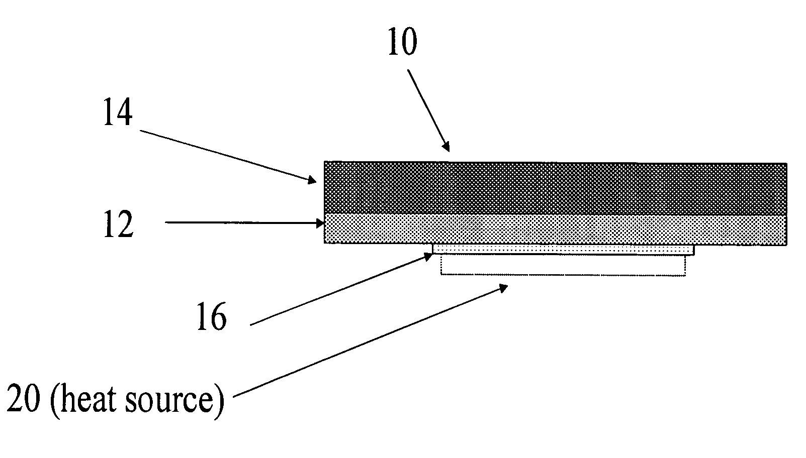
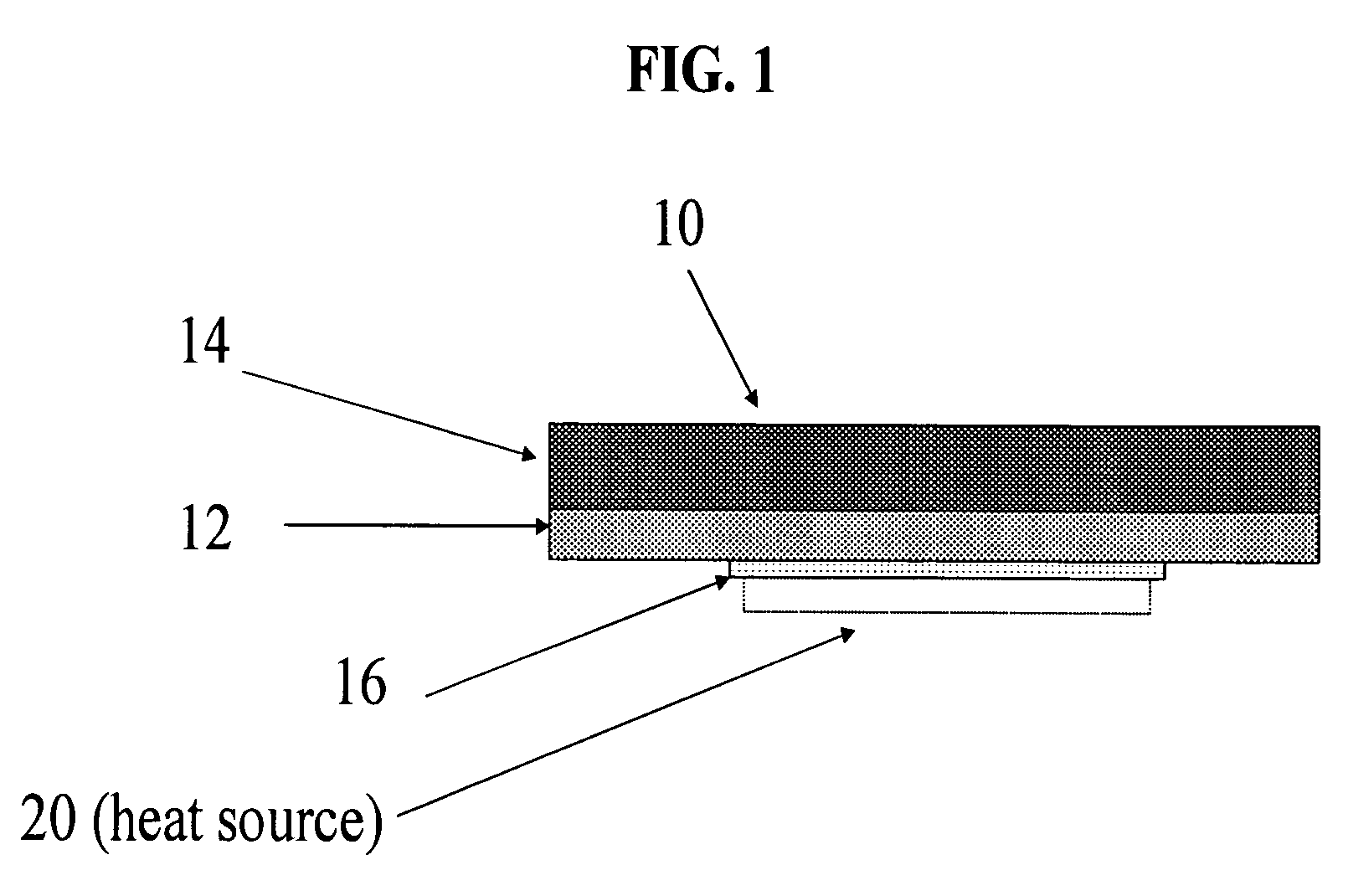
[0008]The thermal interface structure 10 of the present invention is of a multilayer construction comprising a core 12 composed of high conductivity metal such as, for example, copper, or a composition of any high conductivity metal alloy and is of a configuration having opposite sides with a soft filler material 14 disposed on one side thereof and a phase change material 16 disposed on the opposite side. The soft filler material 14 is of a thickness sufficient to permit the thermal interface structure 10 to accommodate a variable spacing between a heat source 20 and a heat sink (not shown) of up to 300 mils.

[0009]The phase change material 16 is formed as a layer in the interface structure 10 having a surface 21 with a surface area which defines its footprint which is smaller than the surface area or footprint of the metallic core 12 and smaller than the corresponding footprint of the gap filler 14 each of which, as shown in FIG. 1, should be considerably larger in dimension than th...


PUM

PropertyMeasurementUnit
thicknessaaaaaaaaaa
thicknessaaaaaaaaaa
thicknessaaaaaaaaaa

Abstract

The thermal interface structure of the present invention is suited for use in a non-referenced die system between a heat source and heat sink spaced up to 300 mils apart and comprises a plurality of layers including a core body of high conductivity metal or metal alloy having opposite sides, a soft thermal interface layer disposed on one side of the core body for mounting against the heat sink and a thin layer of a phase change material disposed on the opposite side of the core body for mounting against the heat source wherein the surface area dimension (footprint) of the core body is substantially larger than the surface area of the heat source upon which the phase change material is mounted to minimize the thermal resistance between the heat source and the heat sink and wherein said soft thermal interface layer is of a thickness sufficient to accommodate a variable spacing between the heat source and the heat sink of up to 300 mils.

Description

FIELD OF INVENTION[0001]This invention is a continuation in part of U.S. Ser. No. 10 / 090,540 filed on Mar. 1, 2002 now U.S. Pat. No. 6,761,928 which, in turn, is a division of U.S. patent application Ser. No. 09 / 513,483 filed Feb. 25, 2000 now U.S. Pat. No. 6,372,997 and relates to thermal interface material structures of multilayer construction with at least one layer having phase change properties.BACKGROUND[0002]Improving heat transfer between sources of heat and associated heat removal hardware has become a critical limitation in many industries. One of those industries particularly affected is electronics, where miniaturization has significantly increased the heat flux required to maintain temperatures at low enough levels to prevent damage to electronic components. Common to many heat removal problems is the requirement to improve the thermal transfer between heat-generating components and heat removal hardware. Since the mating surfaces of these items are not perfectly flat, ...

Claims


Application Information

Patent Timeline
Patent Type & Authority Patents(United States)
IPC IPC(8): H01L23/40B32B15/01B32B3/02B32B7/04H01L23/42H01L23/427
CPCH01L23/4275H01L2924/0002Y10T428/12486Y10T428/12528Y10T428/12396Y10T428/12556H01L2924/00
Inventor HILL, RICHARDSTRADER, JASONLATHAM, JAMES
Owner LAIRD TECH INC
Why Eureka
Try Eureka