Surface-mounted LED and light emitting device

a technology of led and light emitting device, which is applied in the manufacture of semiconductor/solid-state devices, semiconductor devices, electrical devices, etc., can solve the problems of increased power loss of led, increased heat release, and increased heat loss of led, so as to improve heat structure, increase heat release efficiency, and enhance light emission efficiency

Active Publication Date: 2006-07-18
CITIZEN ELECTRONICS CO LTD
View PDF3 Cites 46 Cited by
  • Summary
  • Abstract
  • Description
  • Claims
  • Application Information

AI Technical Summary

Benefits of technology

[0019]In other words, heat conductivity of the glass epoxy material or the like is small to be a degree of few hundredth part of a copper alloy which is a material of the metal core substrate and therefore heat is not transmitted because of a large thermal resistance of the glass epoxy material or the like. Consequently, the utilization of the metal core substrate is indispensable in order to achieve good heat release effect, but the light emitting device is expensive because the material of the substrate is limited, and it is difficult for the metal core substrate to provide wirings in both surfaces thereof, and a high-density mounting is also difficult.

Problems solved by technology

However, when these light emitting elements are used for high brightness and high output, measures for heat release problem.
However, if the driving current is increased, in proportion to this, power loss in the LED is increased, and most of energy is converted into heat.
As a result, the LED is subjected to a high temperature.
Here, because if the temperature is lower, the light emitting efficiency or current-light conversion efficiency becomes higher as the characteristic of the LED, therefore, when the LED is subjected to a high temperature, there will be a problem of lower brightness.
Moreover, when the high-temperature LED continues to be operated, the operating life thereof becomes short, and further there is a possible that transparency of the resin for sealing the LED is decreased, because of change in color due to heat.
Therefore, there is a critical problem of operating life and reliability when the LED is used for the high brightness and high output.
However, although good heat release effect can be expected to the light emitting element 1 shown in FIG. 9, if a metal core substrate or the like of good heat conductivity is used for the printed-circuit board 6, good heat release effect cannot be expected to a printed-circuit board of glass epoxy material or the like which is inexpensive.
Consequently, the utilization of the metal core substrate is indispensable in order to achieve good heat release effect, but the light emitting device is expensive because the material of the substrate is limited, and it is difficult for the metal core substrate to provide wirings in both surfaces thereof, and a high-density mounting is also difficult.
Furthermore, because the metal core substrate is made of a conductive material, the substrate must be insulated by provision of an insulative layer on a surface of the substrate, but because heat conductivity of the insulative layer is insufficient, sufficient heat release effect cannot be expected to the insulative layer.
Because the insulative member 3 is formed by a material of low reflectivity, a force for collecting light by the concave portion is weak and therefore it is not possible to expect large increment of light emitting efficiency.
Moreover, in the light emitting element shown in FIG. 10, there is a problem similar to this.
Moreover, because the structure, in which the heat release member is disposed on the back surface of the printed-circuit board 16, is formed by disposing the printed-circuit board 16 between the base 11 and the heat release member, the base 11 is not coupled thermally with the heat release member, and a structure of the trough-holes in the printed-circuit board 16 is also not effective to enhance heat connection between the base and the heat release member, and therefore significant improvement in heat release effect is not expected.

Method used


Image

  • Surface-mounted LED and light emitting device
  • Surface-mounted LED and light emitting device
  • Surface-mounted LED and light emitting device

Examples


first embodiment

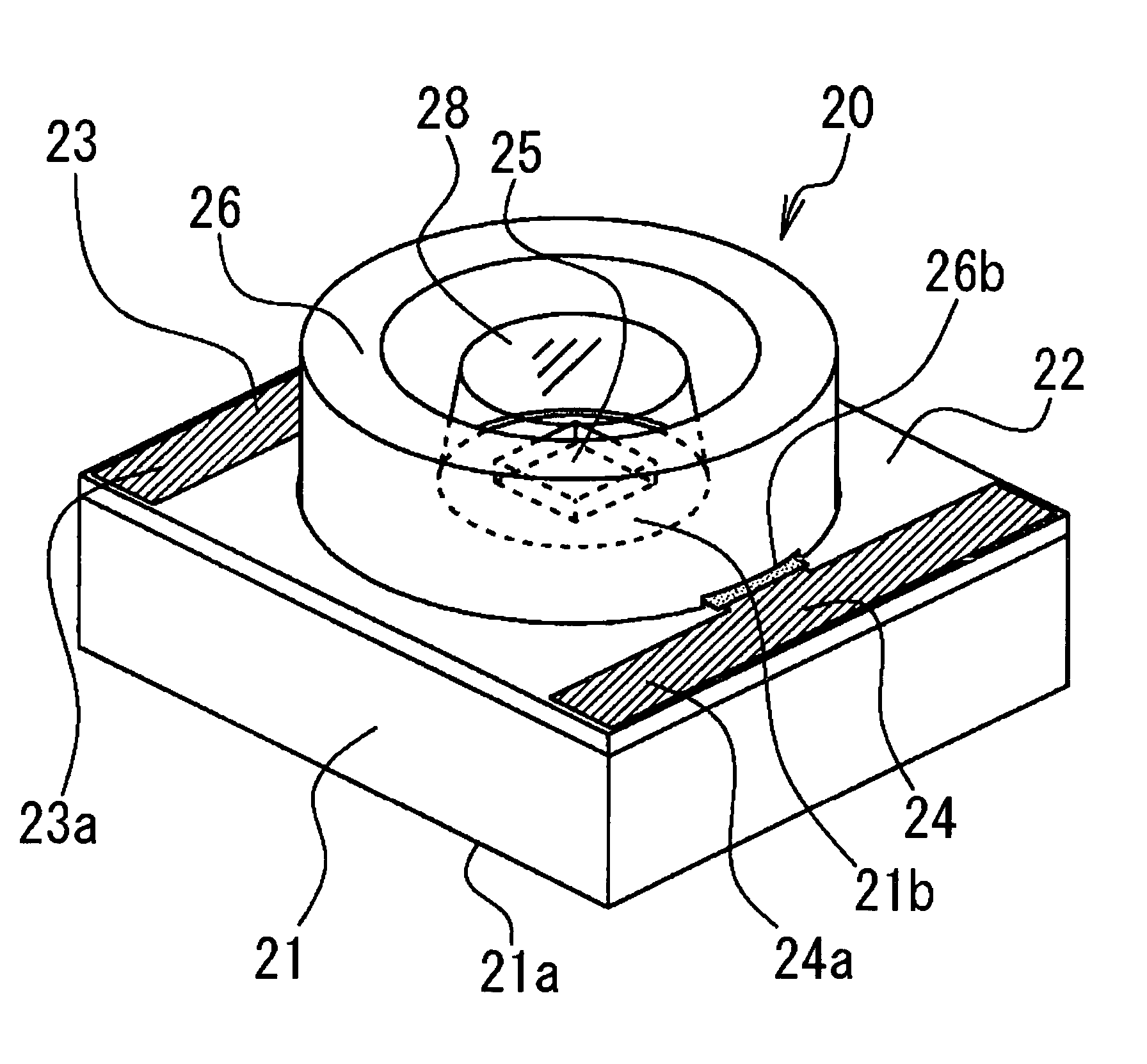
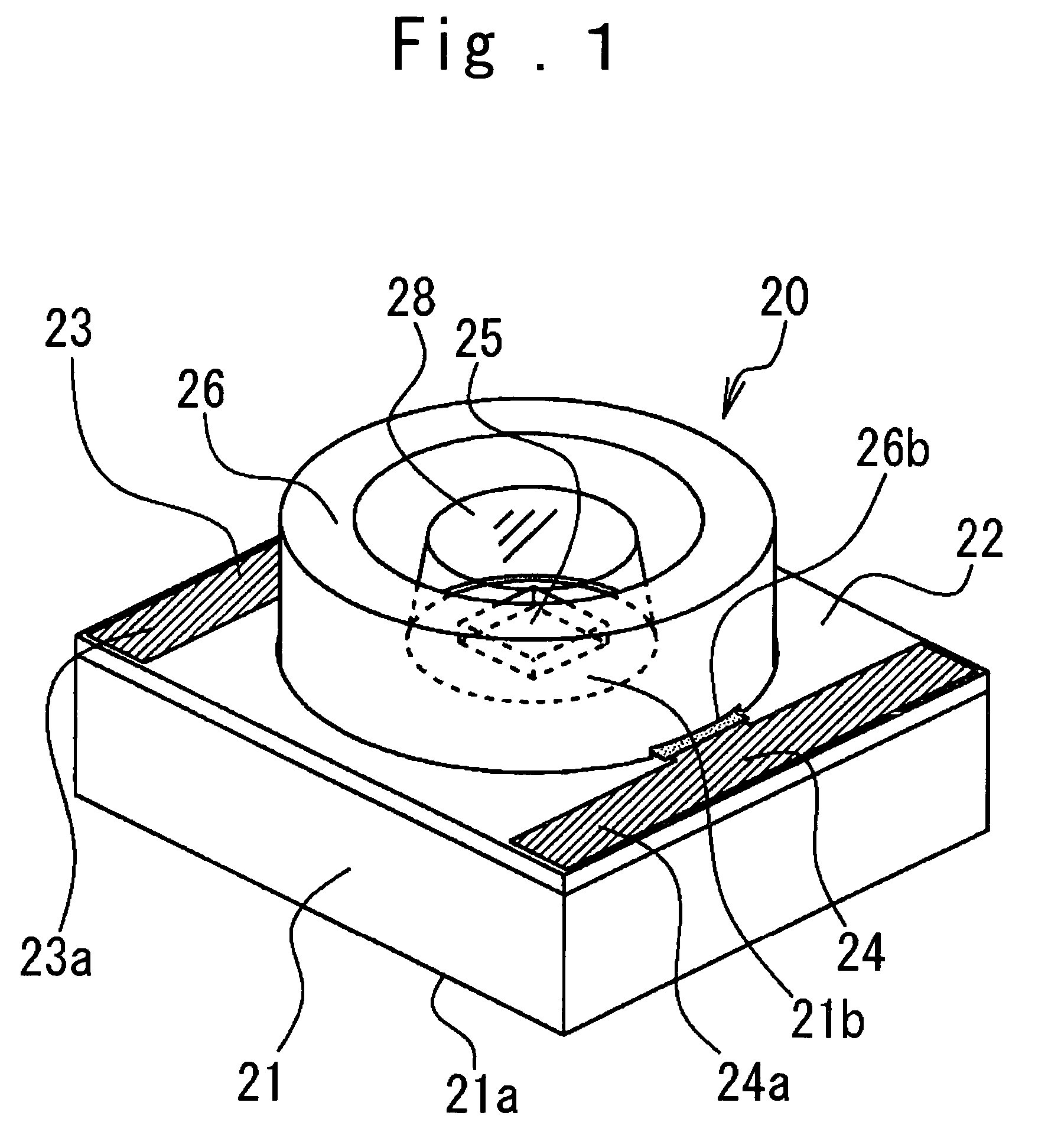
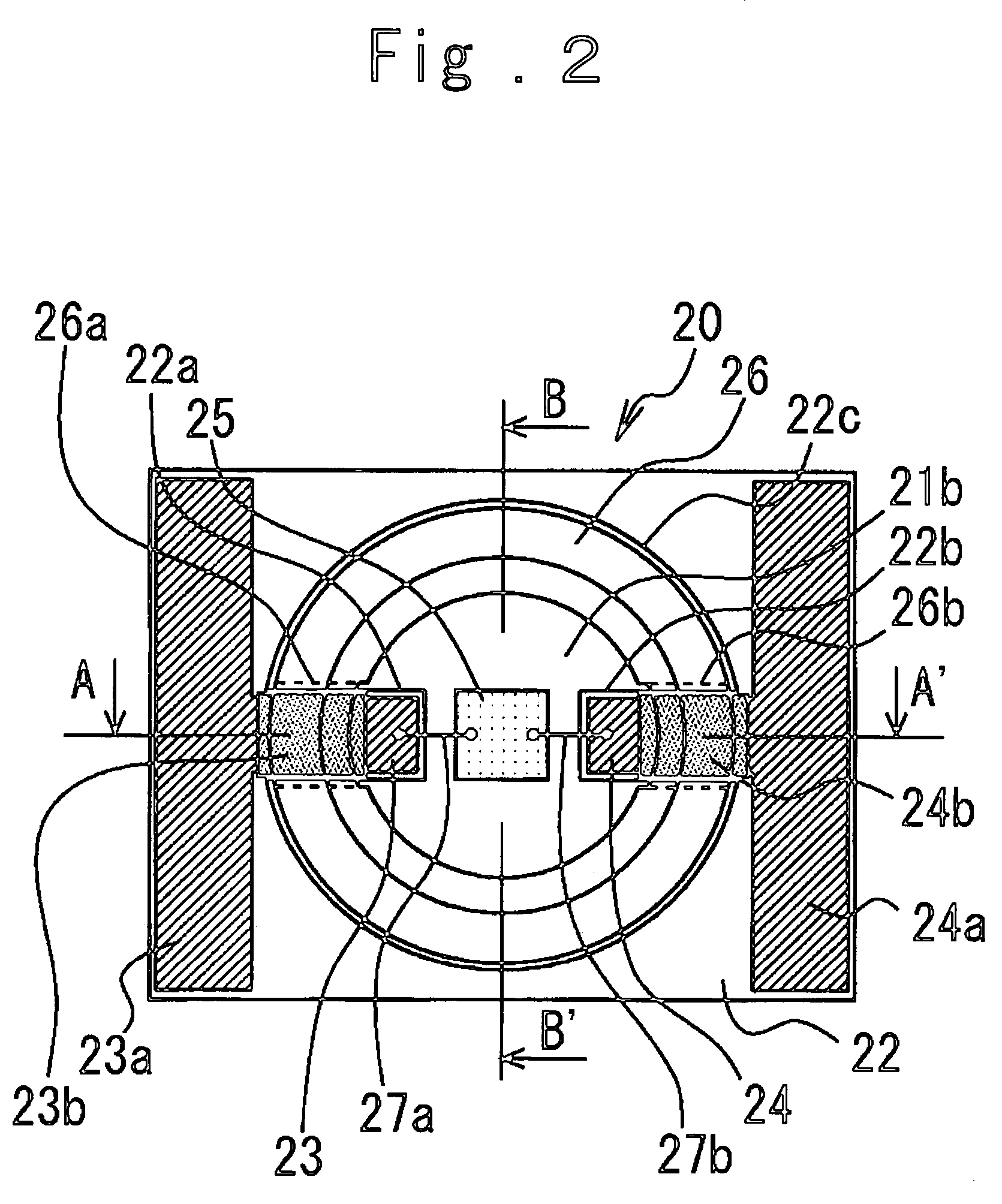
[0043]Next, the structure of the surface-mounted LED in the present invention will be described in more detail referring to FIGS. 3 and 4.

[0044]In FIG. 3, the wiring board protrusions 22a and 22b extend from the vicinity of opposite end portions of the wiring board 22 passing through the lower portion of the reflective frame 26 to the vicinity of the center of the base 21 and are close to the LED chip 25.

[0045]The conductive patterns 23 and 24 on the wiring board protrusions 22a, 22b are also close to the LED chip 25 passing through the lower portion of the reflective frame 26. Meanwhile, because the reflective frame 26 avoids the wiring board protrusions 22a, 22b and the conductive patterns 23, 24 by the reflective frame concave portions 26a, 26b, the disposition of the wiring board protrusions 22a, 22b and the conductive patterns 23, 24 is not blocked by the reflective frame 26.

[0046]The anode and cathode terminals (not shown) of the LED chip 25 are electrically connected with the...

second embodiment

[0055]Next, the present invention will be explained referring to FIGS. 5 and 6.

[0056]In the drawings, the same numerals are attached to the similar parts as in the first embodiment in FIG. 1 and the overlapped description is omitted.

[0057]In FIGS. 5 and 6, 30 is a surface-mounted LED in the second embodiment of the present invention.

[0058]The wiring board 22 is disposed to run around the heat releasing part 21a on the lower surface of the base 21 from both end surfaces 21c and 21d of the base 21. The conductive patterns 23 and 24 formed on the wiring board 22 are also disposed to run around the wiring board 22 and therefore terminal portions 23b and 24b as electrical connection surfaces are formed on the lower surface of the base 21. As a result, the terminal portions 23b and 24b are connected electrically and mechanically with the outside printed-circuit board by the surface-mounting, as described hereinafter, to enable a driving current to supply to the LED chip 25 by means of the...

third embodiment

[0060]Subsequently, the present invention will be explained referring to FIG. 7.

[0061]In FIG. 7, the same numerals are attached to the similar parts as in the first embodiment of the present invention and the overlapped description is partially omitted.

[0062]In FIG. 7, 40 is a light emitting device according to the present invention, which is composed of the surface-mounted LED 20, a printed-circuit board 41 as a substrate and two heat release members 42 and 43 each made of a material having heat conductivity.

[0063]The printed-circuit board 41 has conductive patterns 41a each comprising a copper foil or the like and a mounting hole 41b which is generally circular. Here, the surface-mounted LED 20 is disposed to be fitted in the mounting hole 41b of the printed-circuit board 41, and the terminal portions 23a and 24a of the surface-mounted LED 20 and the conductive patterns 41a of the printed-circuit board 41 are electrically and mechanically connected by soldering 45 as connecting me...


PUM


Abstract

A surface-mounted LED including a base having heat conductivity, an insulative wiring board fixed to the base and including a conductive pattern and a mounting hole, a light emitting element chip mounted on a mounting area exposed by the mounting hole of the wiring board, and a reflective frame having heat conductivity and fixed to the base and thermally coupled therewith, to surround the light emitting element chip, heat generation from the light emitting element chip being released through both the base and the reflective frame, or either one thereof.

Description

CROSS REFERENCE TO THE RELATED APPLICATION[0001]The application claims the priority benefit of Japanese Patent Application No.2003-202747, filed on Jul. 29, 2003, the entire descriptions of which are incorporated herein by reference.BACKGROUND OF THE INVENTION[0002]1. Field of the Invention[0003]The present invention relates to a light emitting element on which a light emitting diode (hereinafter referred to as LED) is loaded and a light emitting device using the light emitting element, more specifically, to a surface-mounted LED improved to increase heat release efficiency and light emitting efficiency and also to a light emitting device using it.[0004]2. Description of Related Art[0005]Conventionally, an LED, which is a semi-conductor formed by a chemical compound is widely utilized as a light emitting element, with a characteristic of long operating life and miniaturization. Because an LED of semi-conductor of gallium-nitride system compound for emitting blue color is developed a...

Claims


Application Information

Patent Timeline
Patent Type & Authority Patents(United States)
IPC IPC(8): H01L27/15H01L33/58H01L33/60H01L33/62H01L33/64
CPCH01L33/60H01L33/64H01L33/486H01L2224/48091H01L2924/00014
Inventor ISHII, HIROHIKOIMAI, SADATO
Owner CITIZEN ELECTRONICS CO LTD
Why Eureka
Try Eureka