Tracking of a tunable laser over output discontinuities

a tunable laser and discontinuity technology, applied in the field of tracking the wavelength of tunable lasers, can solve the problems of discontinuity in the output wavelength of the laser, interference with wavelength tracking, and high cost of swept tunable lasers that sweep continuously over a wide spectral range, and achieve the effect of improving wavelength resolution

Inactive Publication Date: 2006-07-18
AGILENT TECH INC
View PDF5 Cites 8 Cited by
  • Summary
  • Abstract
  • Description
  • Claims
  • Application Information

AI Technical Summary

Benefits of technology

[0006]An optical system with a tunable laser uses a coarse tracking stage with a free spectral range (“FSR”) greater than the largest expected wavelength discontinuity (“mode hop”) to track the relative output wavelength of the swept tunable laser over output wavelength discontinuities. In one embodiment, a phase detector tracks the phase change of the analog electrical signal of the coarse tracking stage and the output of the phase detector is multiplied to enhance wavelength resolution from the coarse tracking stage. In another embodiment, an optical system with a tunable laser uses a fine tracking stage and a coarse tracking stage to track the relative output wavelength of the swept tunable laser over output wavelength discontinuities. The fine tracking stage provides accurate tracking of the relative output wavelength during the sweep, and the coarse tracking stage tracks the output wavelength across discontinuities. Combining the information obtained from the coarse tracking stage with the information obtained from the fine tracking stage provides accurate relative wavelength tracking of the swept tunable laser over output wavelength discontinuities. Adding a wavelength reference, such as an optical absorption cell, to the optical system provides absolute wavelength information.

Problems solved by technology

Unfortunately, swept tunable lasers that sweep continuously over a wide spectral range are expensive.
Mode hopping generally occurs when the lasing mode suddenly changes, and results in a discontinuity in the output wavelength from the laser that interferes with wavelength tracking.

Method used


Image

  • Tracking of a tunable laser over output discontinuities
  • Tracking of a tunable laser over output discontinuities
  • Tracking of a tunable laser over output discontinuities

Examples


Embodiment Construction

I. Introduction

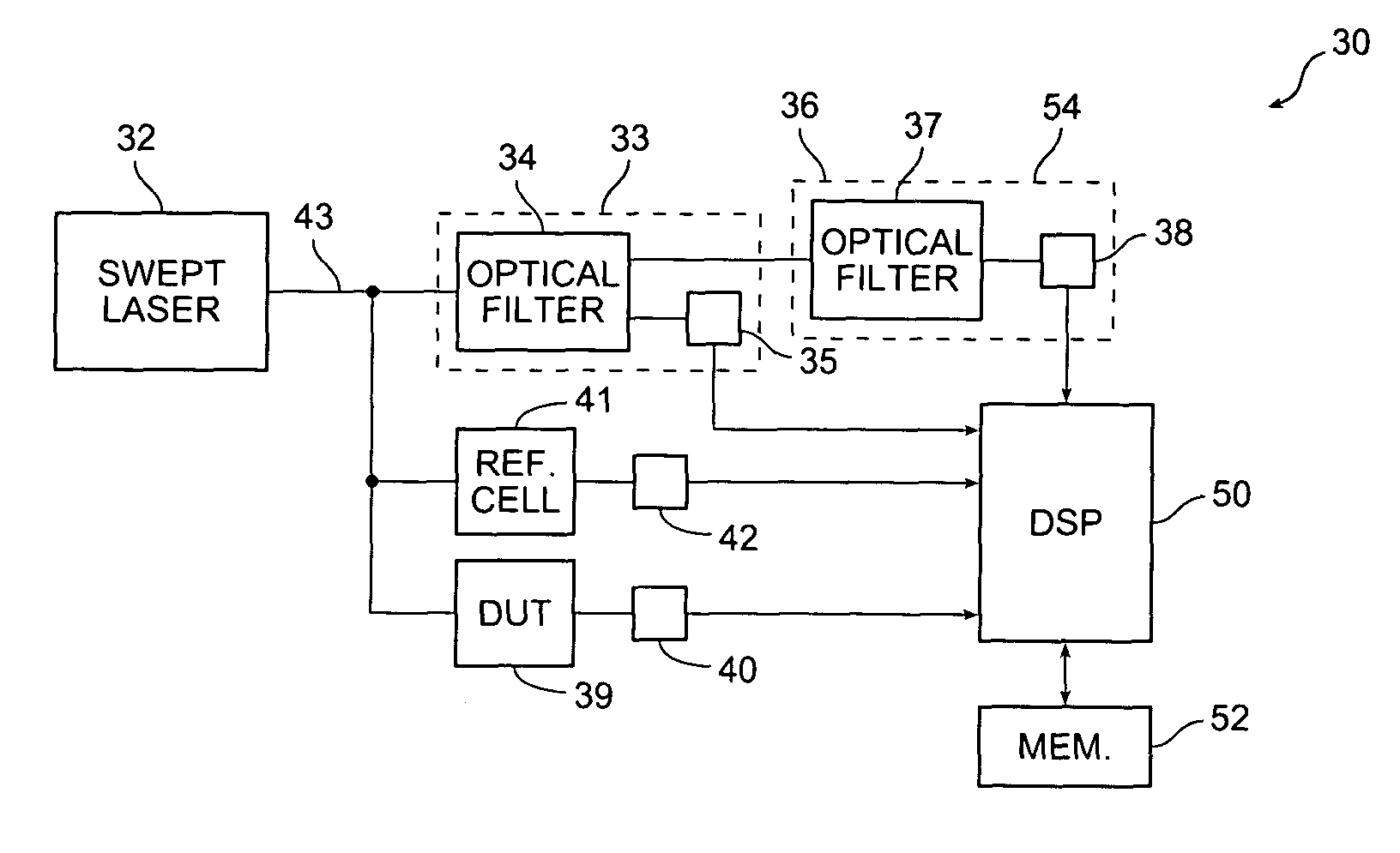
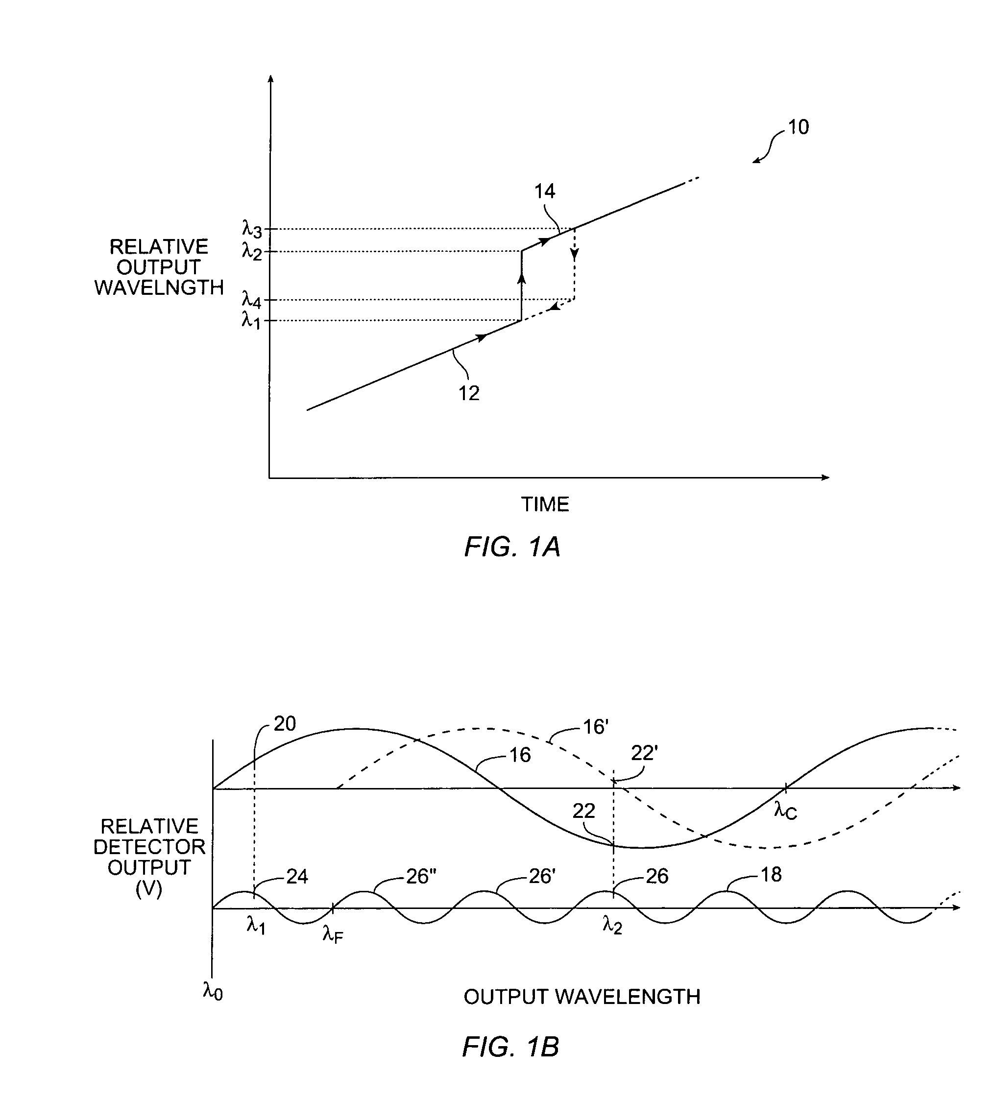
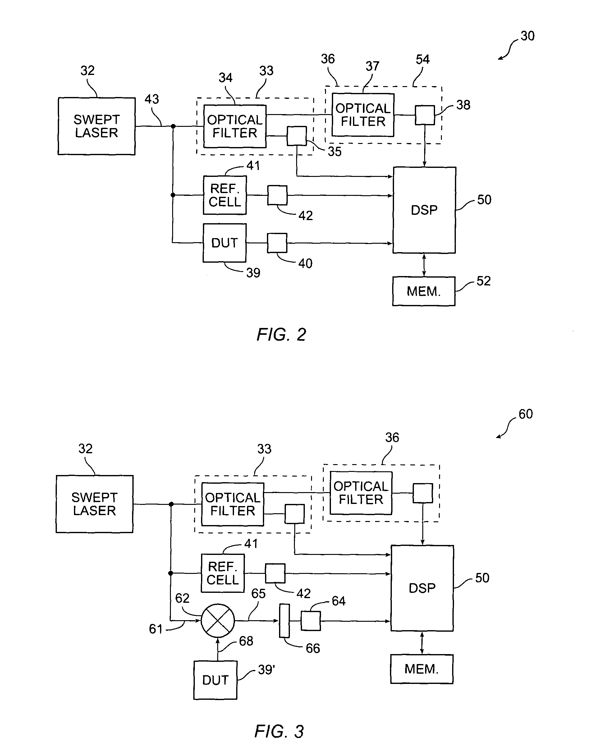
[0014]The present invention provides tracking of a tunable laser over wavelength discontinuities. A coarse tracking stage has a sufficiently large FSR to track the wavelength discontinuity. A phase detector and frequency multiplier between the coarse tracking stage and analog-to-digital converter improves the wavelength resolution of the coarse tracking stage. Alternatively, a fine tracking stage has a sufficiently small FSR to provide the desired relative wavelength resolution. In a further embodiment, a quadrature signal on the coarse tracking stage indicates the direction of movement of the output wavelength, i.e. whether the mode hop results in an increase or decrease in wavelength. In a still further embodiment, a quadrature signal on the fine tracking stage indicates jitter, i.e. whether the output wavelength is locally increasing or decreasing.

[0015]A tracking stage generally has a wavelength-dependent optical filter that produces a periodic wave as a function ...


PUM


Abstract

A tracking stage has an optical filter with a free spectral range greater than the maximum mode hop of a tunable laser. The free spectral range is sufficient to determine the wavelength of the laser output after the mode hop. The output is dithered or a quadrature signal is used to determine whether the mode hop is forwards or backwards. In a further embodiment, a second tracking stage with a shorter free spectral range is coupled to the tunable laser to provide enhanced wavelength resolution. Alternatively, the second tracking stage is omitted and the signal of the tracking stage is amplified to enhance wavelength resolution.

Description

CROSS-REFERENCE TO RELATED APPLICATIONS[0001]Not applicable.STATEMENT REGARDING FEDERALLY SPONSORED RESEARCH OR DEVELOPMENT[0002]Not applicable.REFERENCE TO MICROFICHE APPENDIX[0003]Not applicable.FIELD OF THE INVENTION[0004]The present invention relates generally to tracking the wavelength of a tunable laser, and more specifically to using a tracking stage with a large free spectral range to track the output wavelength of a tunable laser over discontinuities.BACKGROUND OF THE INVENTION[0005]Tunable lasers are used in a variety of applications, such as optical test sets for measuring wavelength-dependent characteristics of optical devices and in optical test instrumentation. In optical heterodyne systems, swept tunable lasers are typically used as the local oscillator. The optical output of the local oscillator is combined with the optical test signal in an optical mixer, and the resulting intermediate frequency is measured. The wavelength of the optical test signal is calculated fr...

Claims


Application Information

Patent Timeline
Patent Type & Authority Patents(United States)
IPC IPC(8): G01B9/02G01J3/45G01M11/00H01S3/10
CPCG01M11/31G01M11/331G01M11/3127
Inventor NORTH-MORRIS, MICHAEL B.LEE, ANTHONY S.
Owner AGILENT TECH INC
Why Eureka
Try Eureka