Creating polynomial division logical devices

a logical device and polynomial division technology, applied in the direction of cad circuit design, electric/magnetic computing, instruments, etc., can solve the problems of logic with maximum operating frequency less than desirable for real-time calculation of crcs in certain applications, data contains errors, undesirable delays, etc., to achieve the effect of improving the performance of the logical devi

Active Publication Date: 2006-07-18
KEYSIGHT TECH SINGAPORE (SALES) PTE LTD
View PDF7 Cites 17 Cited by
  • Summary
  • Abstract
  • Description
  • Claims
  • Application Information

AI Technical Summary

Benefits of technology

[0009]A method according to a second embodiment of the invention creates a logical device performing polynomial division for a given n-degree polynomial. The polynomial division includes calculating a next n-term remainder for an incoming data unit having d terms. The method includes creating code using a high level description language directly describing synthesizable logic for performing the polynomial division. The polynomial division includes automatically extracting a subset of data terms for calculating each of the next remainder terms. The next remainder is then calculated by performing a logical XOR operation on the subset of data terms with a subset of relevant remainder terms calculated for a preceding data unit. The method further includes implementing the logic on a target device. Preferably, the XOR operation includes a pipelined XOR operation with a pre-definable number of pipeline stages, the pipelined XOR operation operating on the subset of data terms. Pipelining may improve performance of the logical device.

Problems solved by technology

If the two CRCs do not match, then the data contains an error.
A limitation of this method of creating CRC calculators is each time a new CRC generator polynomial (i.e. a polynomial with more or less terms) is to be used in the CRC calculator, a designer must use the code generator to produce new HDL code suitable for that polynomial and data word width combination.
This consumes valuable programming resources and ultimately results in an undesirable delay between identifying a new generator polynomial and word / bus width combination and providing a suitable CRC calculator circuit.
In addition to these limitations, the code produced using existing methods for creating a CRC calculator results in logic with maximum operating frequencies which are less than desirable for real time calculation of CRCs in certain applications.
Further, they do not allow the designer to make a trade off between the maximum frequency of operation and silicon area, using a single value setting that is specified as a parameter that is passed to the HDL code module.

Method used


Image

  • Creating polynomial division logical devices
  • Creating polynomial division logical devices
  • Creating polynomial division logical devices

Examples


Embodiment Construction

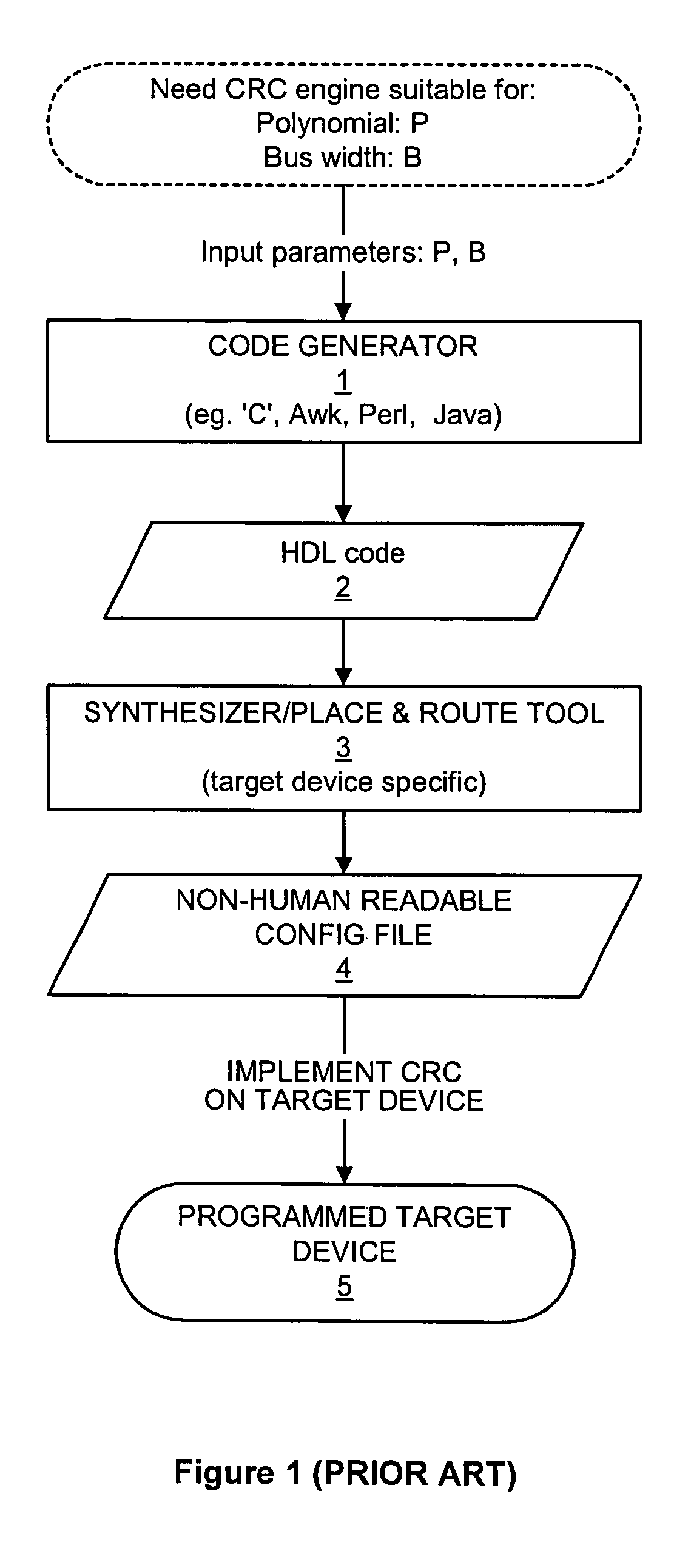
[0018]FIG. 1 illustrates steps involved in creating a CRC calculating device using the prior art methodology. Firstly, a designer is provided with specifications for a desired CRC calculating device, namely the polynomial P and bus width B. Given these constraints, the designer uses a code generator to generate hardware description language (HDL) code which describes the functionality of the CRC calculating device for that specific polynomial and data-bus width combination P and B. Code generators use a range of standard programming languages such as ‘C’, Awk, Perl and Java.

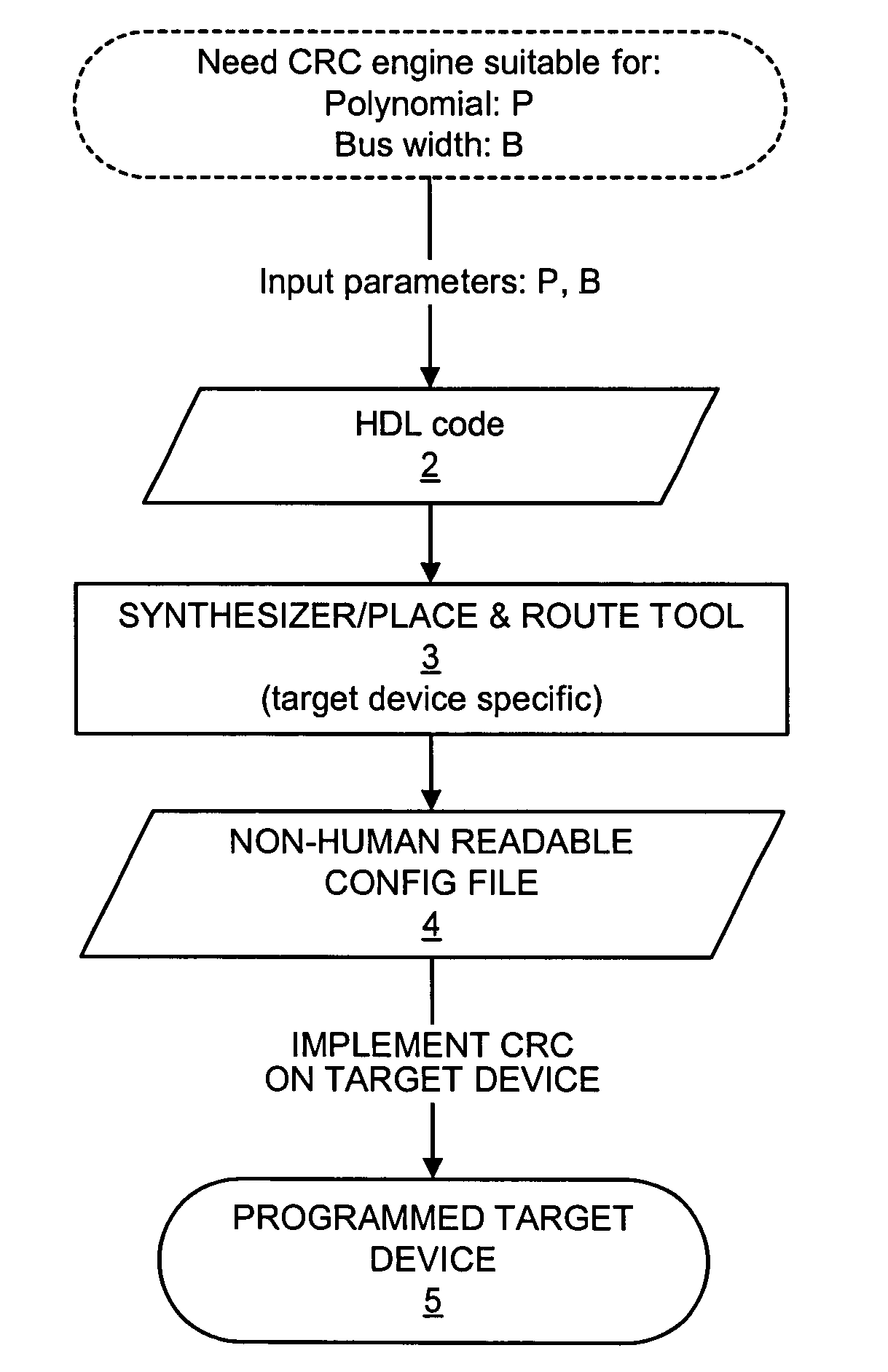
[0019]The HDL code generated by the code generator is then used by a tool such as a “synthesizer” and “place and route tool” to create a configuration file for use by a machine which implements the logic procedure on the programmable target device. Accordingly, the configuration file is usually not readable by humans.

[0020]Using the prior art method, designing a CRC calculating device was at least a two step proc...


PUM


Abstract

A method of creating a logical device performing polynomial division includes using a hardware description language to build code directly describing synthesizable logic for performing the polynomial division. The logic is then implemented on a target device. The code receives as inputs a parameter identifying a polynomial and a parameter identifying a number of data bits for which the polynomial division is performed. For a given n-degree polynomial, performing the polynomial division includes calculating a next n-term remainder for a data unit having d terms.

Description

FIELD OF THE INVENTION[0001]The field of the invention relates to creating logical devices for performing polynomial division. In particular, it relates to a method of using a hardware description language to build code which can be directly synthesized to create a logical device for performing polynomial division and optionally optimizing code using pipelined stages to achieve a maximum operating frequency in the logical device. The polynomial division has applications in calculating a Cyclic Redundancy Check for an m-bit data word, in error correction schemes and in scramblers.BACKGROUND TO THE INVENTION[0002]A cyclic redundancy check (CRC) is used to detect errors in stored or transmitted data. A CRC is calculated using an algorithm which divides the data block by a generator polynomial to produce a remainder. This remainder is the CRC and it is usually appended to the data block before it is transmitted or stored. When the block of data with the appended CRC is received or retri...

Claims


Application Information

Patent Timeline
Patent Type & Authority Patents(United States)
IPC IPC(8): G06F17/50G06E1/00G06E3/00G06F15/18G06G7/00
CPCG06F17/5045G06F30/30
Inventor SAVAGE, PAUL
Owner KEYSIGHT TECH SINGAPORE (SALES) PTE LTD
Why Eureka
Try Eureka