EGR cooler

a cooler and egr technology, applied in the field of egr coolers, can solve the problems of insufficient whirling force of the exhaust gas, affecting the function of the soot in the exhaust gas gathering to the whirling axis, and affecting the performance of the cooling system, so as to achieve superior eventual performance value on heat exchange efficiency, less pressure loss, and superior immun performance value

Inactive Publication Date: 2006-07-25
HINO MOTORS LTD +1
View PDF14 Cites 13 Cited by
  • Summary
  • Abstract
  • Description
  • Claims
  • Application Information

AI Technical Summary

Benefits of technology

[0011]Such inclination angle of the spiral protrusion set to 26°–50° is slightly inferior in imtial performance value on heat exchange efficiency in comparison with an inclination angle of less than 26°, but keeps the exhaust gas in a state so as to have less pressure loss and causes it to flow smoothly with a tendency of the soot not to accumulate on the inner periphery of the tube, and therefore is superior in eventual performance value on heat exchange efficiency after deterioration; in view of long use thereafter, it turns out that there is a prolonged time period with good heat exchange efficiency maintained.
[0014]Moreover, according to the invention, preferably the inner periphery of the tube is formed with a plurality of strands of spiral protrusions running without crossing and with phases peripherally shifted with respect to each other. This enables the axial pitch of the protrusions to be decreased with an inclination angle of the spiral protrusion of more than 26°, whereby whirling force of the exhaust gas can be increased without increasing the pressure loss.

Problems solved by technology

In fact, it has been ensured by the inventor's experiments that the inclination angle of spiral protrusion being set to less than 26° increases the pressure loss so that soot tends to accumulate in the tube, resulting in a substantial lowering in performance.
Moreover, insufficiency of whirling force afforded to the exhaust gas remarkably impairs the function of the soot in the exhaust gas gathering to the whirling axis.
As a result, inversely there may be a tendency of the soot to accumulate on the inner periphery of the tube.

Method used


Image

  • EGR cooler
  • EGR cooler
  • EGR cooler

Examples


Embodiment Construction

[0023]Now embodiments of the invention will be described on the basis of the drawings.

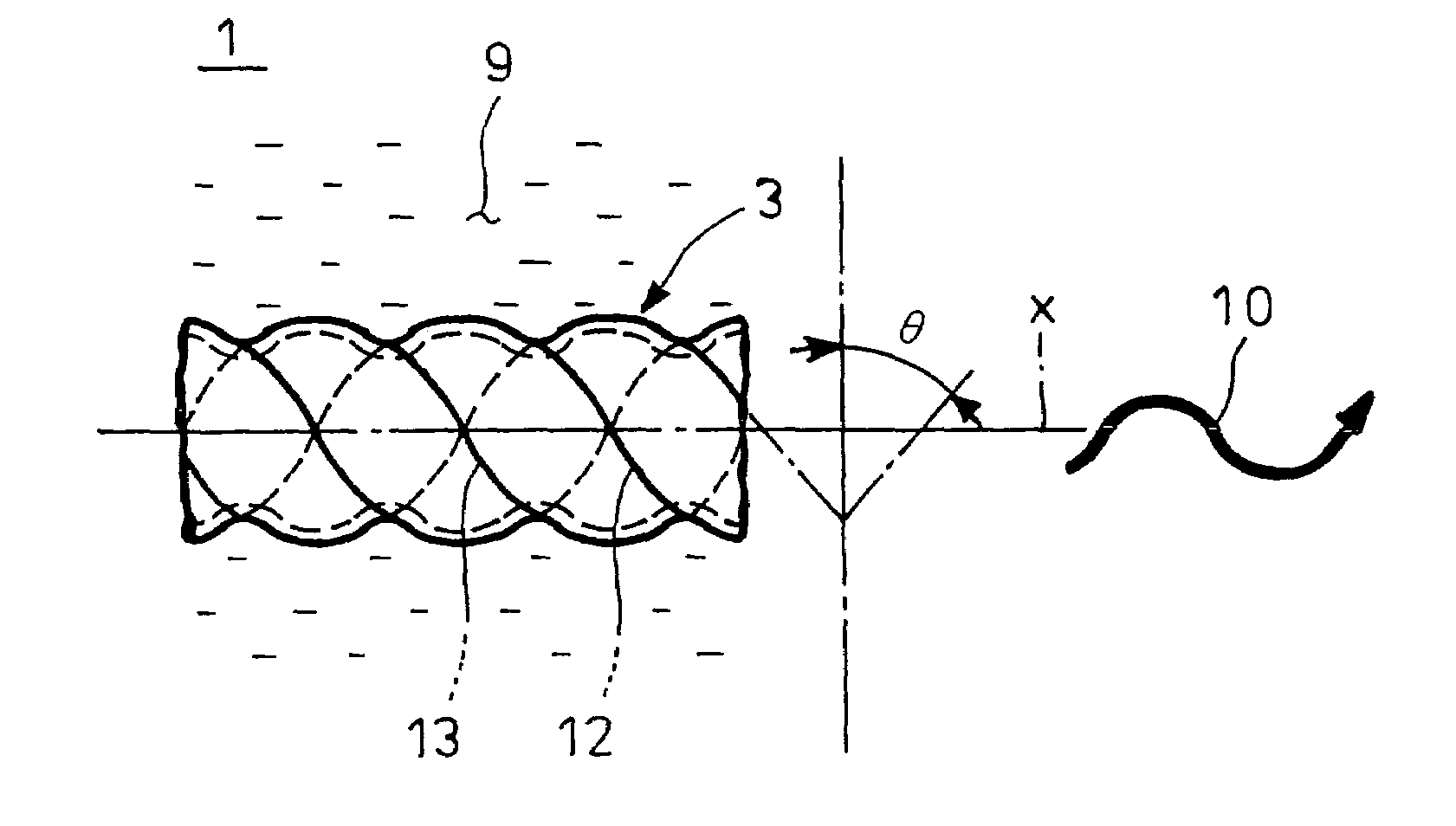
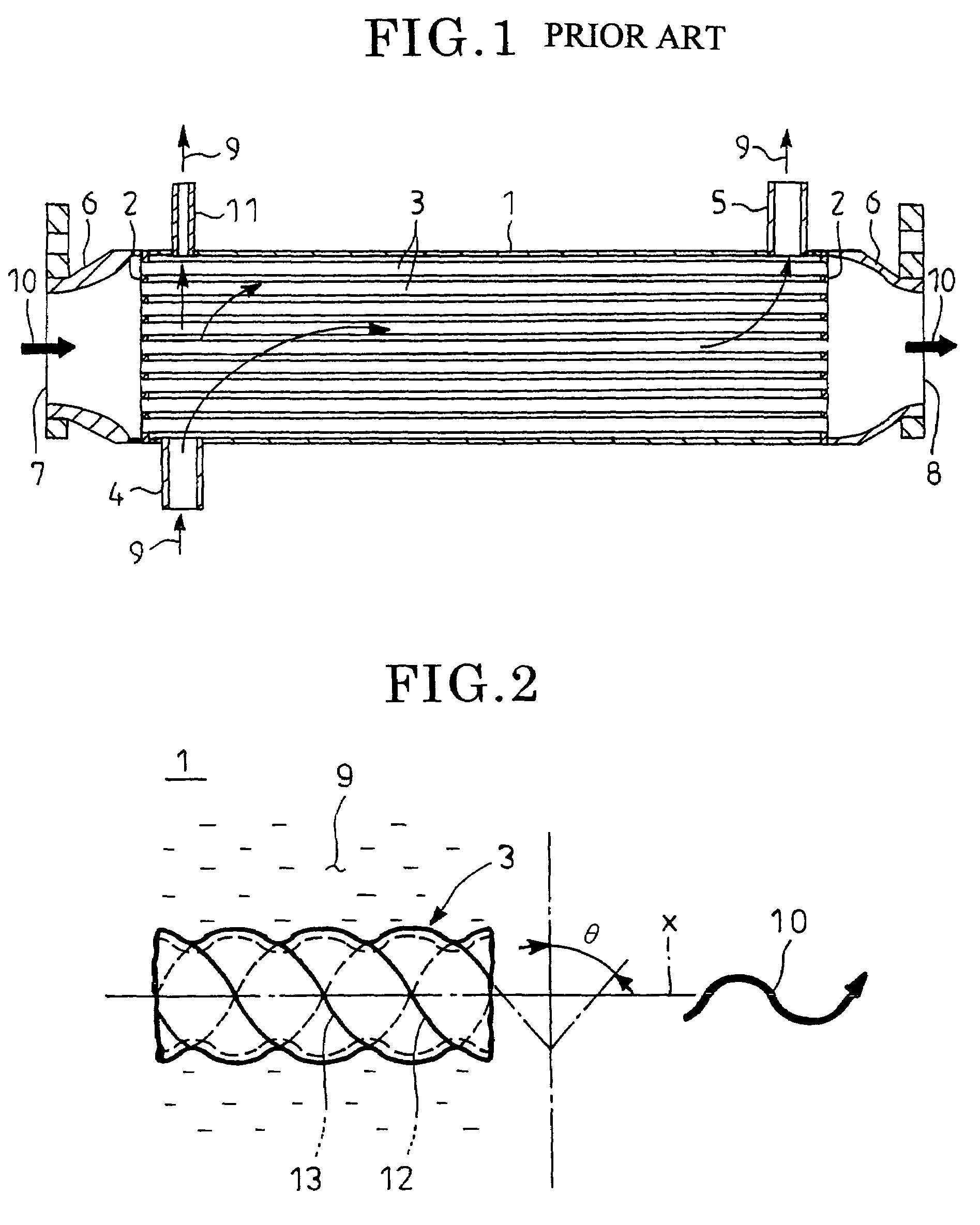
[0024]FIG. 2 shows an embodiment according to the invention in which parts similar to those in FIG. 1 are designated by the same reference numerals.

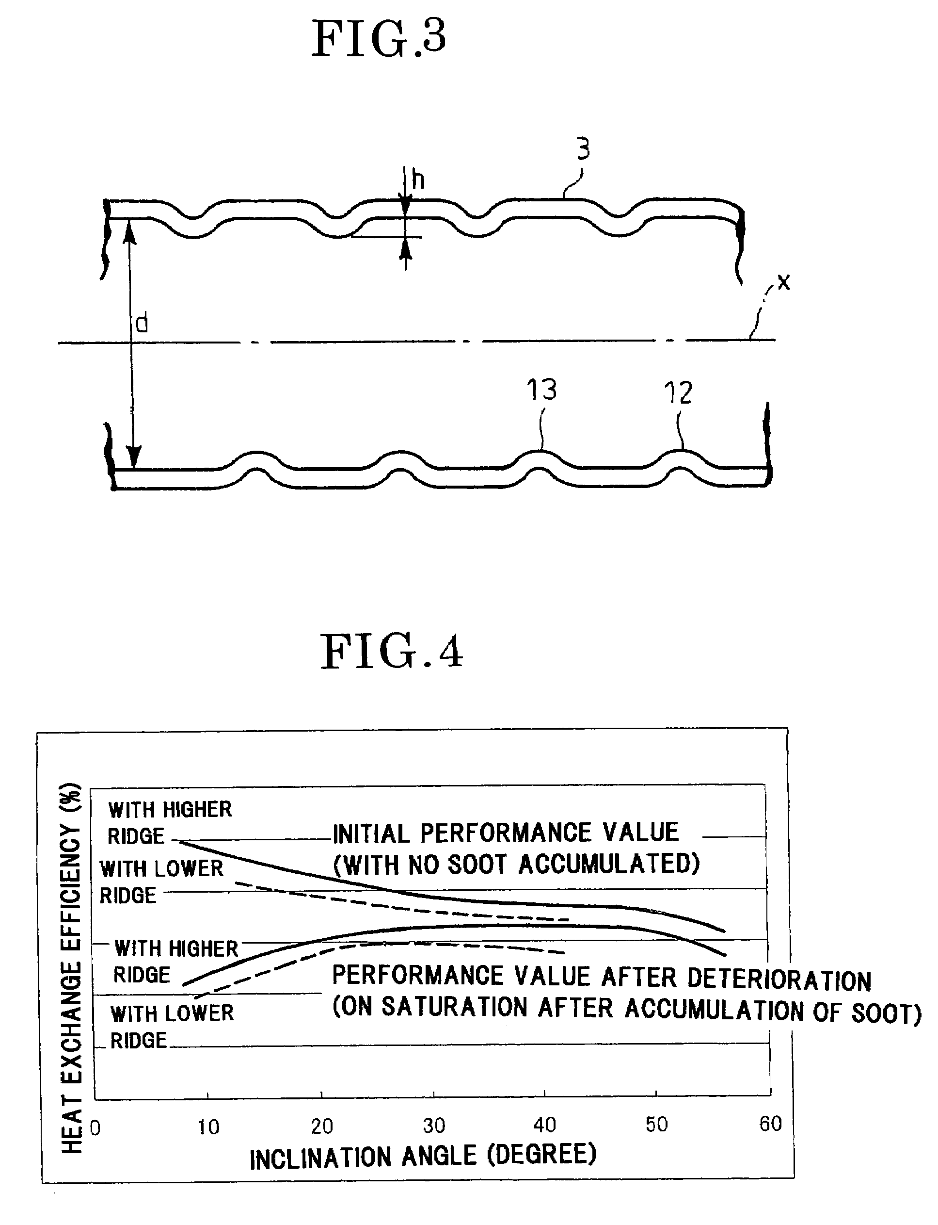
[0025]As shown in FIG. 2, this embodiment is directed to an EGR cooler constructed substantially in the same manner as described above with respect to FIG. 1, and an inner periphery of the tube 3 through which exhaust gas 10 passes is formed with a plurality of streaks of spiral protrusions 12 and 13 with inclination angle θ being in a range of 26°–50° relative to a plane perpendicular to an axis of the tube 3. In the example shown, two streaks of spiral protrusions 12 and 13 run without crossing and with phases peripherally shifted 180° with respect to each other.

[0026]If the tube 3 is thin in terms of wall thickness, the spiral protrusions 12 and 13 may be formed by spirally indenting the tube 3 from outside by means of, for example, a roll having spi...


PUM


Abstract

An EGR cooler has tubes and a shell for enclosing the tubes. Cooling water is supplied into and discharged from the shell and exhaust gas from a diesel engine is guided into each of the tubes so as to conduct heat exchange of the exhaust gas with the cooling water. An inner periphery of each of the tubes is formed with spiral protrusions each having an inclination angle in a range of 26°–50° to a plane perpendicular to an axis of the tube.

Description

TECHNICAL FIELD[0001]The present invention relates to an EGR cooler attached to an EGR apparatus, which recirculates exhaust gas from a diesel engine to suppress generation of nitrogen oxides, so as to cool the exhaust gas for recirculation.BACKGROUND ART[0002]Known is an EGR apparatus which recirculates part of exhaust gas from an engine in a vehicle or the like to the engine to suppress generation of nitrogen oxides. Some of such EGR apparatuses are equipped with, midway of an exhaust gas recirculation line to the engine, an EGR cooler for cooling the exhaust gas since cooling the exhaust gas to be recirculated to the engine will drop the temperature of and reduce the volume of the exhaust gas to lower the combustion temperature in the engine without substantial decrease in output of the engine, thereby effectively suppressing generation of nitrogen oxides.[0003]FIG. 1 is a sectional view showing an example of the EGR coolers in which reference numeral 1 denotes a cylindrical shel...

Claims


Application Information

Patent Timeline
Patent Type & Authority Patents(United States)
IPC IPC(8): F02M25/10F02M25/00F02M25/07F28D7/16F28F1/06F28F1/40F28F1/42
CPCF02M25/0701F02M25/0737F28D7/16F28F1/06F28F1/42F28F1/426Y02T10/121F28D21/0003F28F2210/06F02M26/50F02M26/32
Inventor YAMASHITA, YOJI
Owner HINO MOTORS LTD
Why Eureka
Try Eureka