
Re-locatable partial discharge transducer head

a partial discharge and transducer head technology, applied in the direction of instruments, vibration measurement in solids, specific gravity measurement, etc., can solve the problems of increasing the partial discharge level of the solid thermoset filled transformer, increasing the partial discharge level, and further degradation of the insulation, so as to prevent the egress of mineral oil, increase the frictional engagement, and prevent the effect of mineral oil egress

Inactive Publication Date: 2006-07-25
TRANSGRID +1
View PDF13 Cites 25 Cited by
  • Summary
  • Abstract
  • Description
  • Claims
  • Application Information

AI Technical Summary

Benefits of technology

[0017]The present invention is directed to a device that, in certain circumstances, can economically monitor for occurrences of partial discharge in high voltage electrical equipment. Whilst not necessarily portable, the device can preferably be easily and quickly re-located from one transformer to another with only a brief outage.
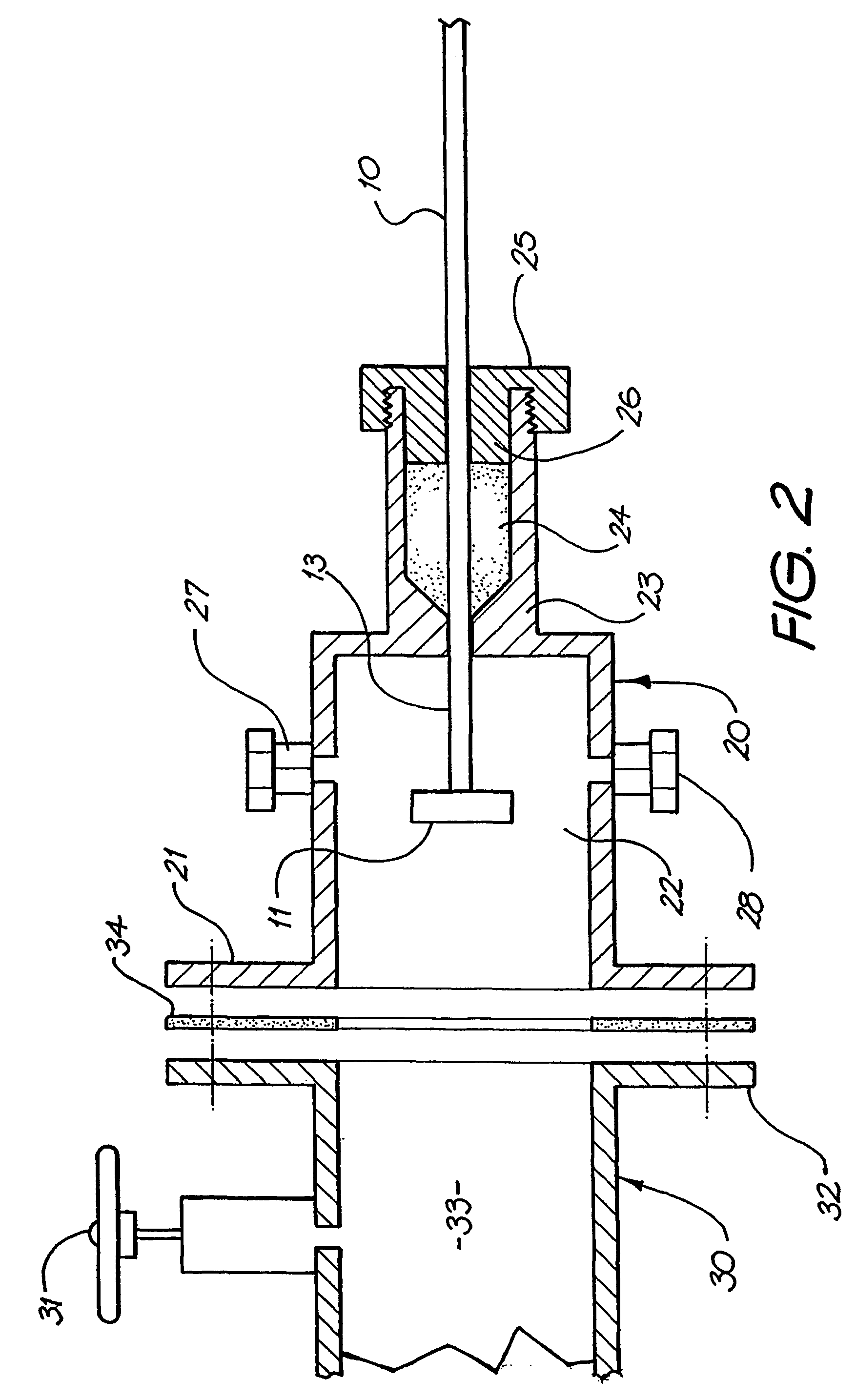
[0053]When it is desired to adjust the extent to which the elongate member is inserted into the transformer, the gland cap can be partially relatively unscrewed so reducing the frictional engagement between the packing material and the elongate member. The elongate member can then be further inserted or retracted as is required.

Problems solved by technology

Any degradation of the insulation, such as electronic and ionic plasma erosion of solid insulation surrounding an air bubble occluded due to faulty manufacture, can result in increasing levels of partial discharge within the solid thermoset filled transformer.
Such increased partial discharge leads to further degradation of the insulation which in turn leads to increasable levels of partial discharge.
Continued degradation of the insulation can result in severe discharges, short-circuit faults or a catastrophic failure due to an explosion of the gases, for example, hydrogen, acetylene and ethylene, produced as chemical by-products of the degradation process.
Such failure can result in reduction or loss of supply (outage) to the power system, incur considerable expense for the replacement or repair of the transformer and also present a serious risk to nearby personnel and the environment.
Partial discharge in transformers can also occur due to faulty manufacture and or mechanical or electrical fatigue.
Partial discharge in transformers can also arise due to windings becoming loose within the transformer.
Wear and tear suffered by the tap connectors and backlash in the tap changer can also cause partial discharges and arcing.
Faults in the bushings can also result in partial discharges.
For example, a detected partial discharge having a magnitude of 50 pC would normally be ignored at normal voltage operations, a reading of 500 pC would be viewed with some concern, whilst a reading of 500 pC would be considered potentially dangerous.
However, there is always some delay between the sampling and the analysis in the laboratory.
There is also delay in carrying out diagnosis based on this analysis.
These measurements can, however, normally not be undertaken in a substation location due to the high level of electrical noise interference.
Making reliable readings with these instruments also requires considerable skill.
While able to detect such signals, one problem with the device described in WO 94 / 28566 was that electrical noise within the transformer would generate randomly occurring radio signals that lead to the triggering of false alarms on occurrences of partial discharge.
Shutting down a transformer based on a false alarm is clearly undesirable and costly.
In the case of relatively cheaper small transformers or where it is desired to institute screening by monitoring for partial discharge of transformers already in use, the costs of mounting a fixed head transducer arrangement and monitoring the transformer may be uneconomic.

Method used


Image

  • Re-locatable partial discharge transducer head
  • Re-locatable partial discharge transducer head
  • Re-locatable partial discharge transducer head

Examples


Embodiment Construction

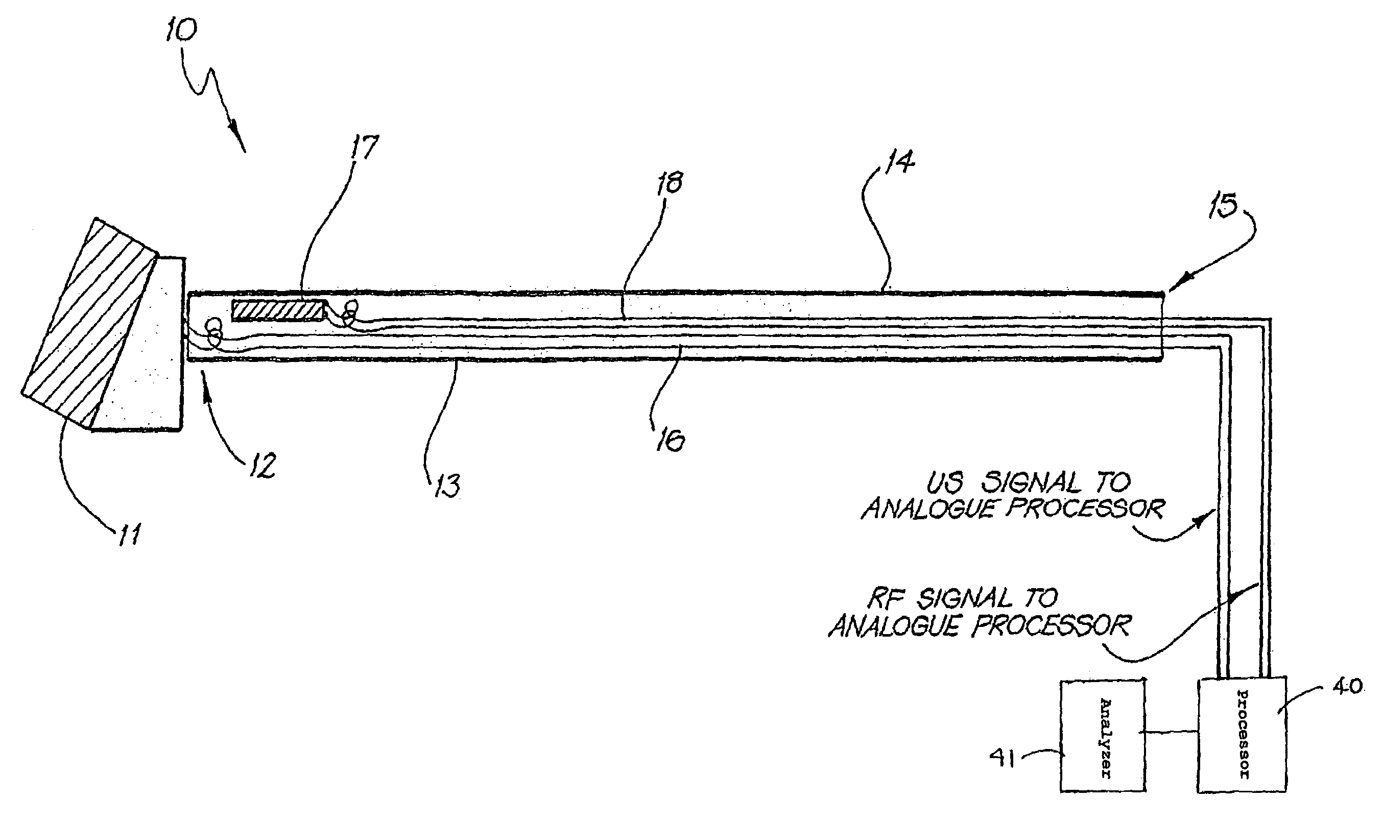
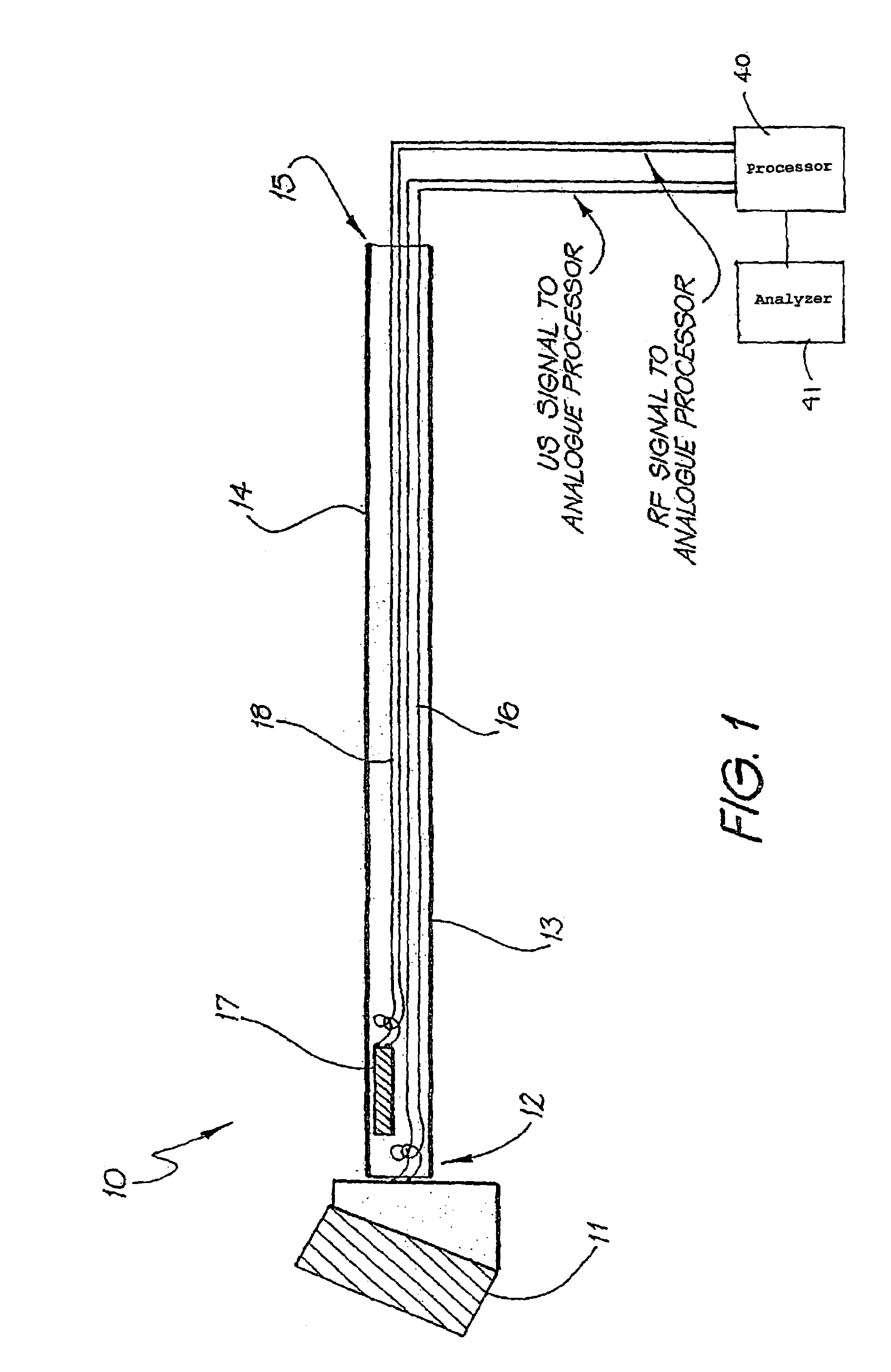
[0061]A transducer probe according to the present invention for use in the detection of occurrences of partial discharge in on-line high voltage electrical equipment, such as transformers, is depicted generally as 10 in FIG. 1.

[0062]The probe 10 includes an ultrasonic transducer 11 mounted at one end 12 of an elongate electrically rated glass fibre rod 13. The rod 13 has the form of a cylindrical tube with a central lumen 14 running therethrough from the one end 12 to a distal end 15.

[0063]The depicted ultrasonic transducer 11 is a ceramic / polymer composite having a 1–3 geometry. The ceramic within the transducer 11 is lead zirconate titanate (PZT). The polymer in the composite is a thermosetting epoxy resin. It will be appreciated that other suitable piezoelectric materials, including piezoelectric ceramics and polymers could be utilised as the ultrasonic transducer 11 in the present invention.

[0064]Each face of the composite transducer 11 has an electrode for the accumulation of c...


PUM

PropertyMeasurementUnit
thickness resonant frequencyaaaaaaaaaa
electrically insulatingaaaaaaaaaa

Abstract

An apparatus (10) for detecting the occurrence of partial discharge in electrical equipment, such as high voltage transformers. The apparatus comprises a detecting means including an ultrasonic transducer (11) mounted at one end of an electrically insulating elongate rod (13). The ultrasonic transducer (11) is adapted to detect ultrasonic pulses or waves generated by the occurrence of a partial discharge in the electrical equipment. A radio frequency (RF) transducer (17) is also utilized to detect radio frequency (RF) pulses or waves also generated by the partial discharge. The rod (13) can be mounted in the wall of the electrical equipment and so provide a mechanism for adjusting the position of the detecting means within the electrical equipment. The apparatus is also removable from the electrical equipment and re-locatable to other equipment.

Description

FIELD OF THE INVENTION[0001]The present invention relates to a system for monitoring the performance of electrical equipment, such as high-voltage transformers. In particular, the system comprises transducers that can be used to detect and locate faults in the overall insulation of transformers.BACKGROUND OF THE INVENTION[0002]High voltage generator and transmission transformers form an integral part of any electrical power generation, distribution and transmission system. Other transformers, such as rectifier transformers are also used in industrial processes, such as smelting and electro-deposition processes. Also, current transformers (CTs) are used for protection and metering of electricity distribution systems.[0003]The most important part of the insulation for oil filled transformers comprises paper which is wound around the copper windings and the oil itself. There are spacers, washers, seals, lead through plates, taps and bushings, which are also part of the insulation syste...

Claims


Application Information

Patent Timeline
Patent Type & Authority Patents(United States)
IPC IPC(8): H01H9/50G01R31/06G01R1/067G01R31/12H01F27/40H01H33/26
CPCG01R31/1209G01R31/1272H01H33/26H01F27/402H01F2027/406
Inventor UNSWORTH, JOSEPHTALLIS, DAVID
Owner TRANSGRID
Learn More