Substrate holder, and use of the substrate holder in a highly accurate measuring instrument

a technology of substrate holder and measuring instrument, which is applied in the direction of instruments, electrical equipment, geological measurements, etc., can solve the problems of not being able to accurately locate the substrate surface, the focal plane changes, and the substrate is no longer exactly located on the surface of the substrate, so as to minimize the abbé error and high accuracy of the measuring instrumen

Inactive Publication Date: 2006-07-25
LEICA MICROSYSTEMS SEMICON GMBH
View PDF21 Cites 6 Cited by
  • Summary
  • Abstract
  • Description
  • Claims
  • Application Information

AI Technical Summary

Benefits of technology

[0012]The substrate holder according to the present invention and the use according to the present invention of the substrate holder make possible measurement of the substrate in both reflected and transmitted light. The substrate holders are configured in such a way that all the surfaces of the substrates to be measured lie at an identical height. This height is defined in such a way that the surfaces of the substrates lie in the Abbé plane, which minimizes Abbé errors. The substrate holders are configured as frames in which is defined an opening that is delimited by a peripheral rim. Support elements, on which point supports are configured, are provided on the peripheral rim of the opening. In a preferred exemplary embodiment, three support points are distributed correspondingly along the peripheral rim of the opening. The three-point support results in an exact calculation of the mask deflection, which makes possible exact calculation and correction of the position data. The substrate holders are configured such that a different substrate holder is used for each substrate type. The outside dimensions of each substrate holder are the same. The difference arises from the fact that in the substrate holders, the defined openings are correspondingly based on the size of the substrate type used. The support elements and the point supports thereby made available are arranged on the peripheral rim of the openings in such a way that the flat upper surface of the substrate holder aligns with the surface of the substrate. Small deviations from the standard thickness of a substrate type can be corrected by focusing with the optical system of the measuring instrument first on the surface of the substrate and then on the flat upper surface of the substrate holder. From the difference in focal positions it is then possible to ascertain a thickness deviation of the substrate, which is then incorporated into the exact calculation of the mask deflection. A code that allows individual processing of the substrate holder by the measurement and correction software can also be mounted on the substrate holder. Long-term monitoring (drift monitoring and optionally also drift correction) is made possible by integrated reference points. In addition, the substrate holders can be configured such that the total weight of the substrate holder and substrate placed thereon is always approximately the same for the various substrate types. Distortions and deformations at the X / Y carriage and at the mirror body can thereby be kept constant to a first approximation. For this purpose, corresponding programs which correct these constant external influences are provided in a calculation unit of the measuring instrument.

Problems solved by technology

This arrangement has a considerable disadvantage, however, in that it is not very flexible, since only fixed mask sizes can be used or measured in this case.
It is moreover problematic that if masks with different mask thicknesses need to be measured, the focal plane changes and is no longer located exactly on the surface of the substrate.
A disadvantage of this substrate holder is that it is not suitable for transmitted light.

Method used


Image

  • Substrate holder, and use of the substrate holder in a highly accurate measuring instrument
  • Substrate holder, and use of the substrate holder in a highly accurate measuring instrument
  • Substrate holder, and use of the substrate holder in a highly accurate measuring instrument

Examples


Embodiment Construction

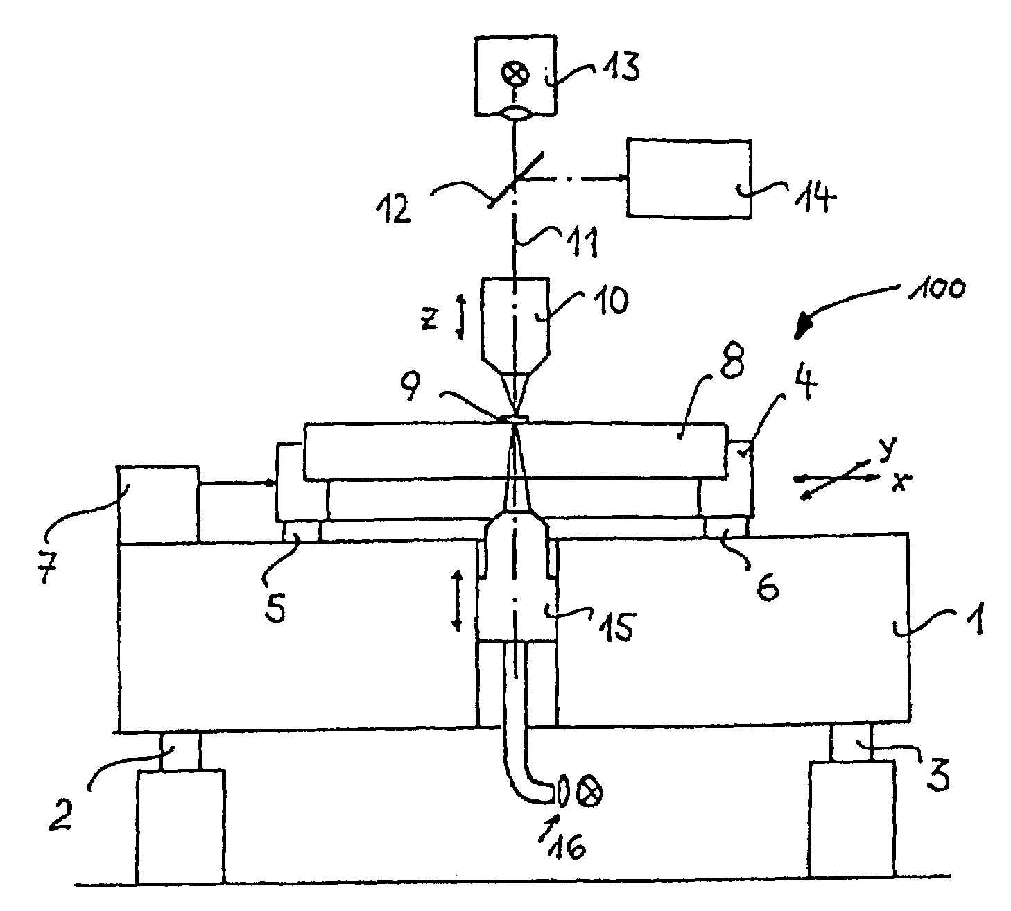
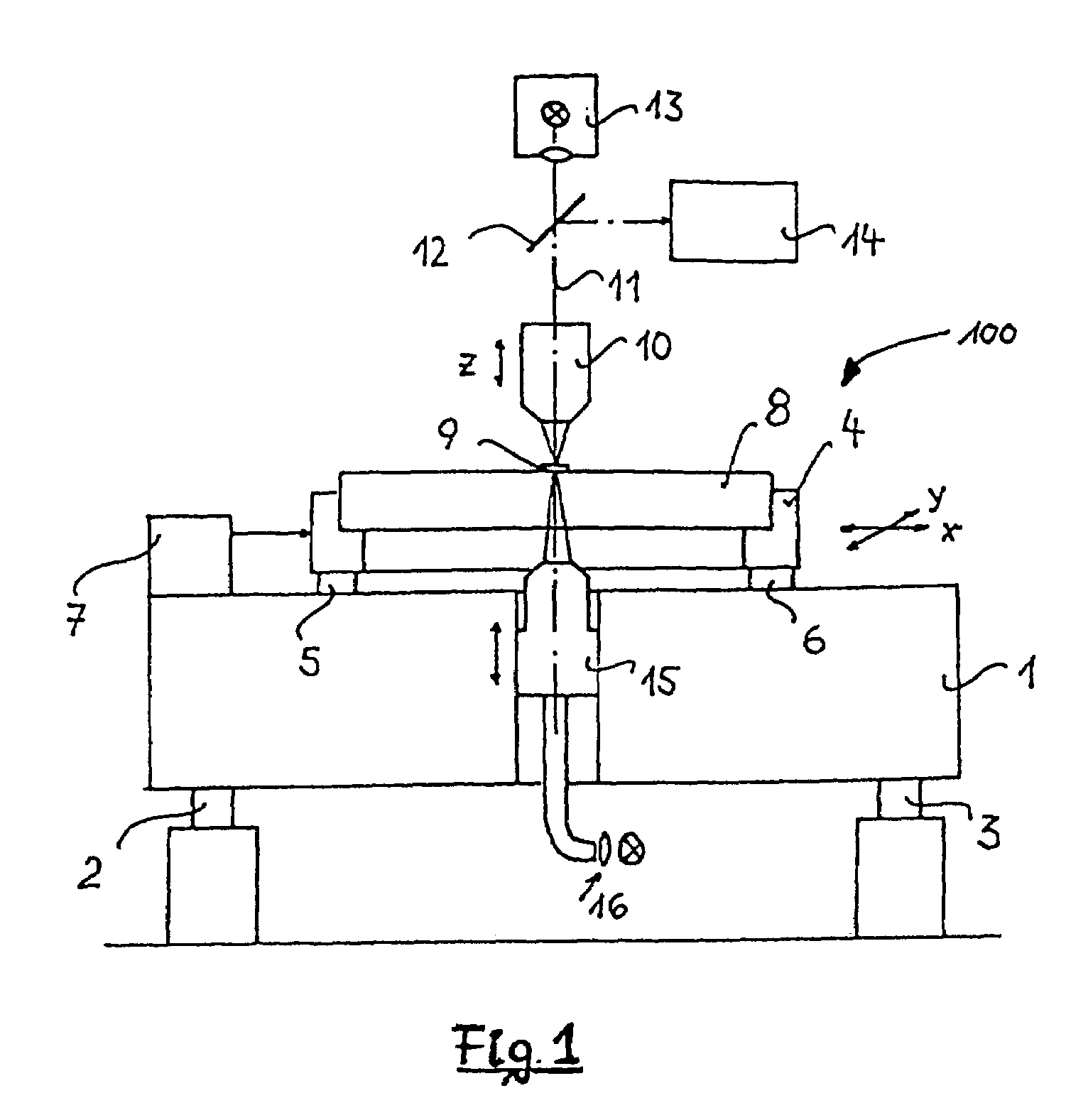
[0020]The highly accurate measuring instrument 100 depicted in FIG. 1 comprises a granite block 1 that is mounted in vibration-damped fashion on bases 2, 3. Configured on granite block 1 is an X / Y carriage (not visible in this view) that is slidingly displaceable in two directions indicated by arrows. A mirror body 4 is placed on X / Y carriage, and advantageously is made of a glass ceramic with a low coefficient of thermal expansion. It is of course also possible to use other materials that possess thermal expansion properties appropriate for the accuracy of the measuring instrument. The drive systems for the X / Y carriage are not depicted. The positions of the X / Y carriage and of mirror body 4 are measured in the X and Y directions with a laser interferometer system 7.

[0021]A substrate holder 8 with substrate (not depicted) is placed into mirror body 4 of the X / Y carriage. The substrate is made, for example, of quartz glass. Patterns 9 are applied onto the substrate surface. Since mi...


PUM


Abstract

The invention discloses a substrate holder (8) that is configured to receive a substrate (20) and can be utilized to determine the thickness deviation of a substrate from the standard thickness of a specific substrate type. The substrate holder (8) comprises a one-piece frame having a flat upper surface (42). An opening (30) that defines a peripheral rim (32) is provided in the substrate holder (8). Receiving elements (34) on which spheres are provided are shaped onto the peripheral rim (32) of the opening (30). A substrate (20) placed into the substrate holder (8) thus comes to rest on the upper surfaces of the spheres. The support elements (34) are arranged on the peripheral rim of the opening (30) in such a way that they lie at the vertices of an equilateral triangle. In addition, the spacing from the upper surface of the spheres to the flat upper surface (42) of the substrate holder (8) is dimensioned such that said spacing corresponds substantially to the standard thickness of the substrate type being used.

Description

CROSS REFERENCE TO RELATED APPLICATIONS[0001]This application is a division of application Ser. No. 09 / 685,772, filed Oct. 11, 2000 now U.S. Pat. Ser. No. 6,816,253 which claims priority of a German filed patent application DE-A-199 48 797.9.FIELD OF THE INVENTION[0002]This invention concerns a substrate holder and the use of the substrate holder according to the present invention in a highly accurate measuring instrument. The invention concerns in particular a substrate holder which is configured in such a way that it is suitable for a defined support of a substrate and thereby contributes to enhancing the measurement accuracy of the highly accurate measuring instrument.BACKGROUND OF THE INVENTION[0003]U.S. Pat. No. 5,671,054 discloses a method and an apparatus for determining the position of patterns on substrates that have a specific thickness. The substrate is placed onto a measurement stage that, in order to support the substrate, has three defined point-like support elements. ...

Claims


Application Information

Patent Timeline
Patent Type & Authority Patents(United States)
IPC IPC(8): G01B11/28G01B11/06H01L21/00H01L21/66H01L21/673
CPCG01B11/06H01L21/67353H01L21/67359H01L21/67253H01L21/67242H01L22/12
Inventor BLAESING-BANGERT, CAROLAKACZYNSKI, ULRICH
Owner LEICA MICROSYSTEMS SEMICON GMBH
Why Eureka
Try Eureka