Agile optical wavelength selection for antenna beamforming

a technology of optical wavelength selection and antenna beamforming, which is applied in the direction of antennas, electrical equipment, etc., can solve the problems of generality of antenna beams and complicating the architecture of such a system

Inactive Publication Date: 2006-08-01
HRL LAB
View PDF13 Cites 63 Cited by
  • Summary
  • Abstract
  • Description
  • Claims
  • Application Information

AI Technical Summary

Benefits of technology

[0011]Embodiments of the described phased array antenna system may have additional switched optical delay lines to provide for additional steering of the antenna beams corresponding to each lens port. The switched delay lines may also provide the ability to achieve steering in other directions. The switched delay lines are preferably located between the optical iris and the RF lens.
[0012]The optical iris used in embodiments of the described phased array antenna system allows the antenna system to adjust the effective beam width associated with a given waveform Exciter or Receiver according to operation modes of the antenna system. For example, it is generally preferred that radar systems operating in a search mode have a narrow effective beam, so that optical iris can be configured to provide such a beam. Alternatively, it is preferred for radar systems operating in a track mode that the beam is wider, so the optical iris can be configured to provide that result. Further, for wideband or multi-band signals and smaller RF lenses, whose size is on the order of the wavelength of the lower signal frequencies, the optical iris may be adjusted for different signal frequencies to compensate for diffraction or inter-port coupling effects. These effects can cause the signal to overlap multiple ports of the RF lens, with the number of ports greater as the frequency is lower.

Problems solved by technology

However, even though the system described in U.S. Pat. No. 5,999,128 provides multiple antenna beams, each antenna beam can generally only be coupled to a single source (i.e., transmitter) or destination (i.e., receiver).
As noted above, prior art multiple beam phased antenna systems typically provide that each antenna beam may only be coupled to a single source or destination, unless additional combinatorial circuitry is used, which further complicates the architecture of such a system.

Method used


Image

  • Agile optical wavelength selection for antenna beamforming
  • Agile optical wavelength selection for antenna beamforming
  • Agile optical wavelength selection for antenna beamforming

Examples


Embodiment Construction

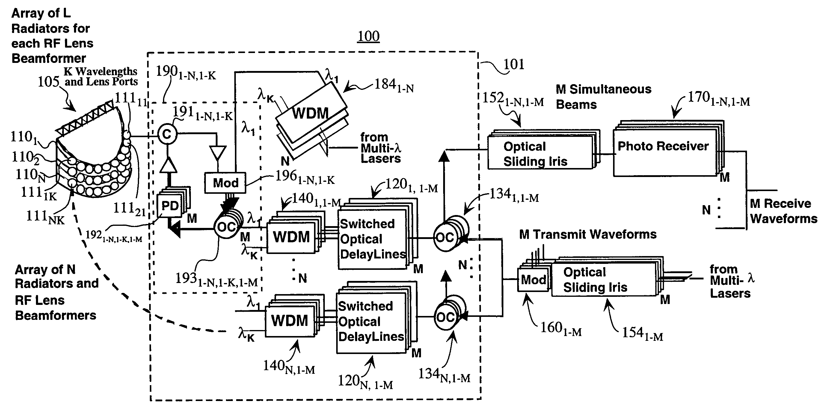
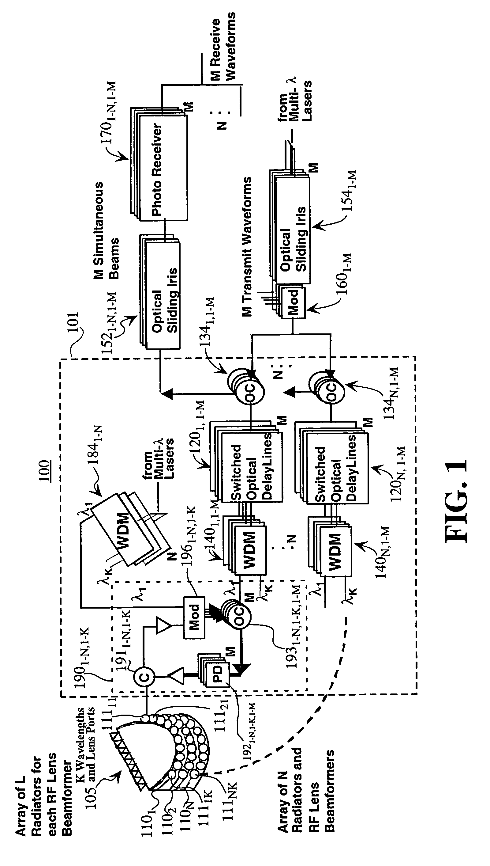
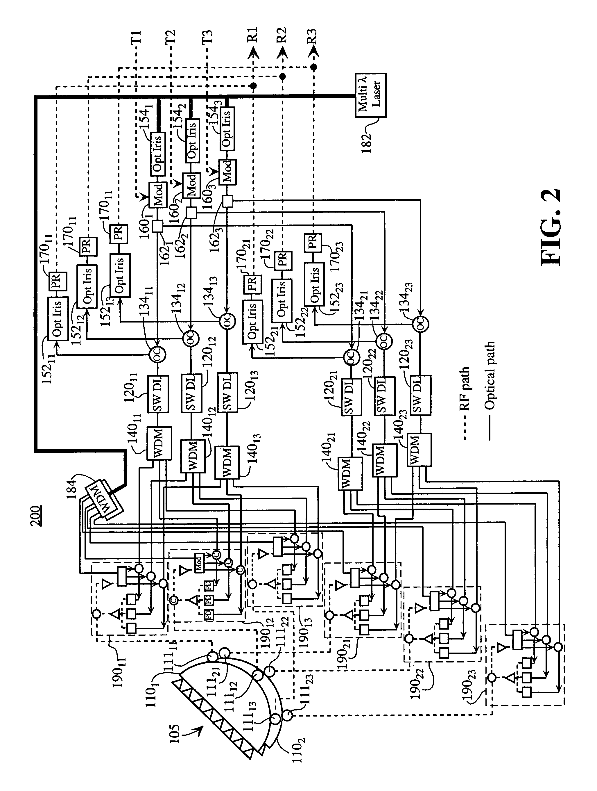
[0024]Embodiments of the present invention provide beamforming systems and methods for forming beams with an array antenna that makes use of RF lens beamformers (such as Rotman lenses, R / 2R lenses or Luneberg lenses) and a multi-wavelength photonic network with optical irises. The beamforming systems and methods also may include switched optical delay lines that are cascaded with the RF lenses. The RF lens beamformers may be implemented as well-known RF structures (such as those described in pages 595–626 of the Handbook of Microwave and Optical Components, Volume 1, edited by K. Chang, J. Wiley & Sons, 1989). The RF beamformers may also be provided by an optical implementation as described in U.S. Pat. No. 6,452,546, issued Sep. 17, 2002 to Stephens, incorporated herein by reference in its entirety.

[0025]Generally, a RF lens beamformer has a set of ports on one side, with those ports connected to the array of antenna elements. The RF lens has a second set of ports located on the ot...


PUM


Abstract

An antenna beamformer consisting of optical irises coupled to Wavelength Division Multiplexers (WDMs). The ports of the WDMs are coupled to lens ports, where each lens port corresponds to a different antenna beam. The optical irises are optical filters with selectable center frequencies and selectable passband widths. Selection of different center frequencies and passband widths enables the selection of different ports of the WDMs, which allows the selection of one or more antenna beams. The beamformer may also have controllable delay lines to provide for additional beam steering.

Description

BACKGROUND[0001]1. Field[0002]The present disclosure relates to steerable antennas such as phase arrays. More specifically, the disclosure relates to a beamforming architecture and a method for forming beams of an array antenna that use radio frequency lens beamformers and a multi-wavelength photonic network with optical irises.[0003]2. Description of Related Art[0004]Phased array antenna systems are widely used in radar, electronic warfare, and radio frequency communication systems. Phased array antenna systems are characterized by the capability to steer one or more antenna beams of the antenna system by controlling the phase of the radio waves transmitted and received by each radiating element of the antenna system. Hence, a phased array antenna system does not have to be mechanically moved to provide antenna beams that move either horizontally, vertically, or in both directions.[0005]Radio Frequency (RF) lens beamformers are known in the art and are commonly used for antenna sys...

Claims


Application Information

Patent Timeline
Patent Type & Authority Patents(United States)
IPC IPC(8): H01Q3/22
CPCH01Q3/2676
Inventor YAP, DANIEL
Owner HRL LAB
Why Eureka
Try Eureka