System for measuring the optical image quality of an eye in a contactless manner

Inactive Publication Date: 2006-08-01
CARL ZEISS JENA GMBH
View PDF19 Cites 43 Cited by
  • Summary
  • Abstract
  • Description
  • Claims
  • Application Information

AI Technical Summary

Benefits of technology

[0025]There are decisive advantages to this combination of interferometric measurement of the length of the eye and analysis of aberrations which can occur through the cornea and possibly also sometimes through the lens predominantly in the paraxial regions with respect to the axis of the eye. A first decisive advantage is offered through the construction itself, which is capable of carrying out both measurements by means of an individual reference point which is generated by a light source and by a corresponding reflection of the light coupled into the eye. Comparability of the measured values and the possibility of a correlation between the measured values with respect to the aberrations and with respect to the length of the eye which are based on the same reference point are provided, so that the quality and therefore the practical use of the measurement results for the operator and the patient can be improved.
[0026]Further, the combination provides an instrument for measuring all quantities of decisive importance for the imaging quality of the eye and, because of its contactless construction, the device also makes it possible during an operation, e.g., insertion of an intraocular lens implant, to carry out corresponding monitoring, quality assurance and, if necessary, correction of the changes performed by the operator.
[0027]The

Problems solved by technology

However, it is disadvantageous that only the length of the eye can be measured by this approach.
Both of the methods mentioned above have in common that they are incapable of detecting greater deviations of the visual system through measurement techniques.
A basic feature of the interferometer consists in that fifty percent of the light is lost at the beam splitter and good perceptibility of the signals is impaired by the resulting a

Method used


Image

  • System for measuring the optical image quality of an eye in a contactless manner
  • System for measuring the optical image quality of an eye in a contactless manner
  • System for measuring the optical image quality of an eye in a contactless manner

Examples


Embodiment Construction

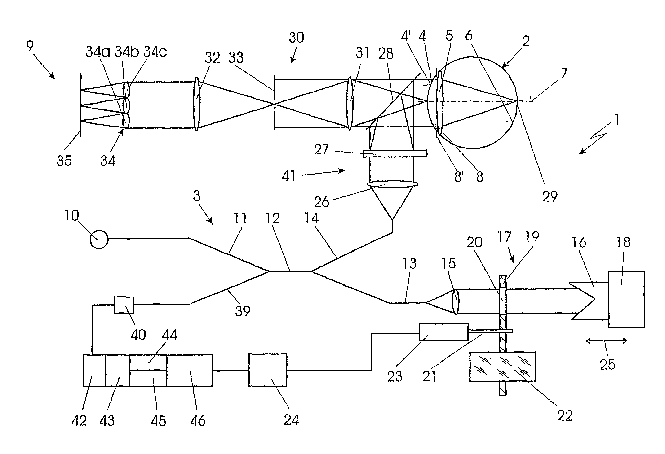
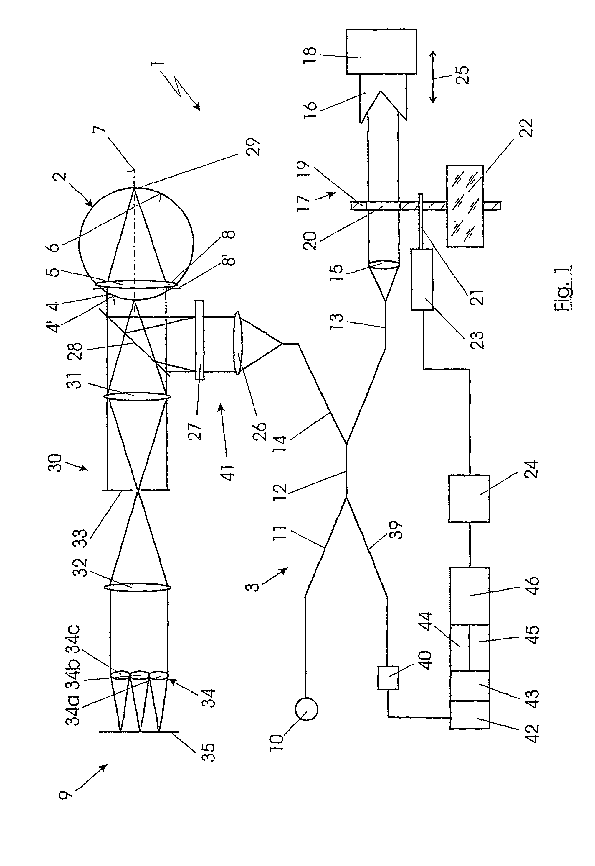
[0037]FIG. 1 shows a possible embodiment form of the system 1 for contactless measurement of the optical imaging quality of an eye 2 with an interferometer 3. The system 1 is to be used primarily for measuring the human eye 2 during and after surgical procedures in the region of the cornea 4 and lens 5. However, it is also conceivable in principle to use the system 1 for measuring similarly constructed eyes 2 of other mammals, since the system 1 works automatically in any case and does not require any feedback from the patient or subject. This also makes the system 1 suitable for use during operations in which the patient is generally at least partly anesthetized, in which case feedback would possibly be difficult.

[0038]The system 1 is provided for simultaneous measurement of aberrations and of a length L of the eye 2 in a contactless manner, that is, without a probe or the like contacting the eye 2.

[0039]By length L of the eye 2 is meant the distance between the surface 4′ of the c...


PUM


Abstract

A system is used for contactless measurement of the optical imaging quality of an eye with an interferometer by which at least one light pulse with a short coherence length is coupled into the eye from a light source. The optical path length of at least one arm of the interferometer is varied for measuring the length of the eye until a typical interference pattern between a reflection of the cornea and a reflection of the retina of the eye occurs in a detector. This interference pattern together with a known path segment of the variation of the optical path length allows conclusions to be made about the length of the eye. The variation of the optical path length is carried out by introducing at least partially optically transparent elements and by at least one element of the interferometer which is movable in a defined manner in at least one of the light paths of the interferometer.

Description

CROSS-REFERENCE TO RELATED APPLICATIONS[0001]This application claims priority of International Application No. PCT / EP01 / 10070, filed Aug. 31, 2001 and German Application No. 100 42 751.0, filed Aug. 31, 2000, the complete disclosures of which are hereby incorporated by reference.BACKGROUND OF THE INVENTION[0002]a) Field of the Invention[0003]The invention is directed to a system for contactless measurement of the optical imaging quality of an eye with an interferometer by which at least one light pulse with a short coherence length is coupled into the eye from a light source.[0004]b) Background of Problems Relating to the Invention[0005]Following operations in the region of the lens of the eye and the comea, for example, cataract operations or refractive procedures on the comea, optical deviations or aberrations can occur in the visual system of the eye which can not be corrected by spherical or astigmatic lenses or cylindrical lenses. Another problem with these aberrations is that ...

Claims


Application Information

Patent Timeline
IPC IPC(8): G01B9/02A61B3/10G01B11/02A61B3/12A61B3/15
CPCA61B3/1005A61B3/12G01B9/0209G01B9/02029G01B2290/35
Inventor HELLMUTH, THOMASTAN, LIENG-CHUONG
Owner CARL ZEISS JENA GMBH
Why Eureka
Try Eureka