High frequency jet nozzle actuators for jet noise reduction

a jet engine and actuator technology, applied in the direction of marine propulsion, vessel construction, instruments, etc., can solve the problems of increasing the causing drag and thrust loss, and protruding, and achieve the effect of not resulting in increased fuel burn of the engin

Inactive Publication Date: 2006-08-01
THE BOEING CO
View PDF9 Cites 16 Cited by
  • Summary
  • Abstract
  • Description
  • Claims
  • Application Information

AI Technical Summary

Benefits of technology

[0006]The present invention is directed to a noise reduction system employing a plurality of deformable flow-altering components that are disposed adjacent a downstream edge of an exhaust nozzle of a nacelle which houses a jet engine. In one preferred form, the flow-altering components comprise a plurality of transduction actuator elements that are deformable (i.e., deployable) in response to the application of an electric current thereto. In a preferred embodiment, an alternating current is applied to the transduction actuators to cause an oscillating motion. The oscillating motion causes the transduction a...

Problems solved by technology

The drawback with the above-described, present day chevrons is that such devices, being fixed in their positions, protrude into the exhaust flow at all times during operation of the jet engine.
This, of course, generates drag and a loss of thrust.
Thus, with present day noise reduction systems that employ fixed chevrons or other like fixed elements, a tradeoff occurs between the needed noi...

Method used


Image

  • High frequency jet nozzle actuators for jet noise reduction
  • High frequency jet nozzle actuators for jet noise reduction
  • High frequency jet nozzle actuators for jet noise reduction

Examples


Embodiment Construction

[0015]The following description of the preferred embodiment(s) is merely exemplary in nature and is in no way intended to limit the invention, its application, or uses.

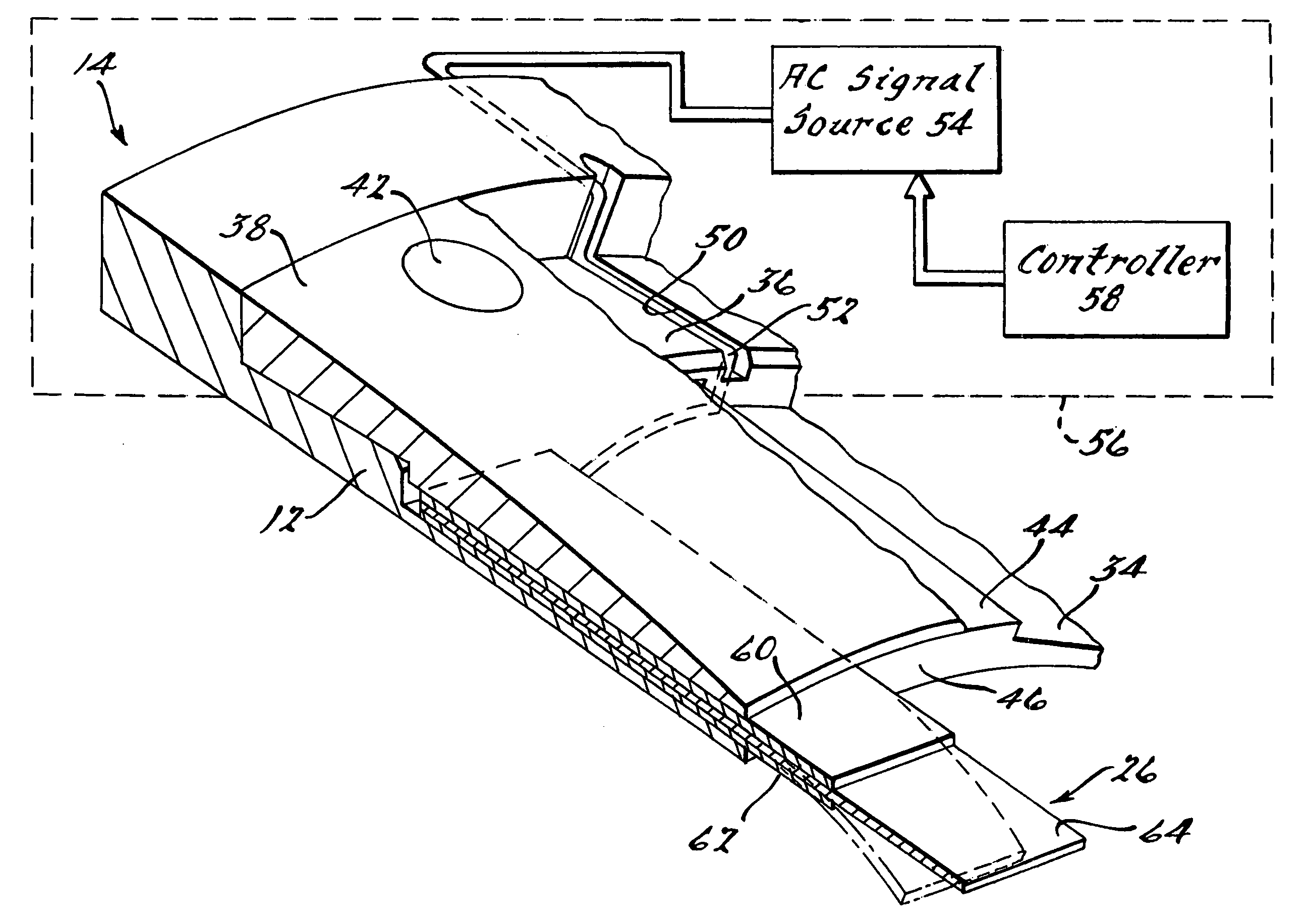
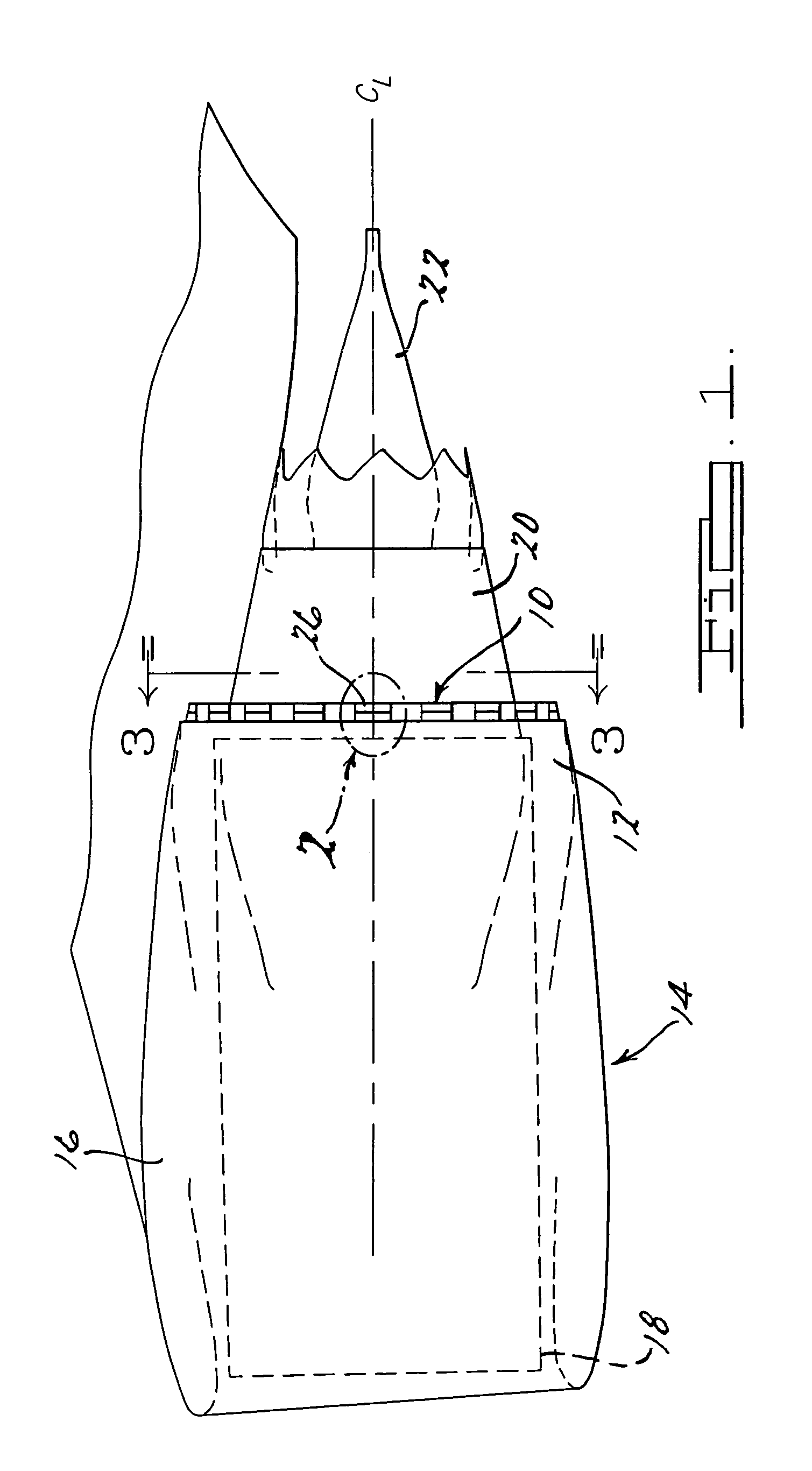
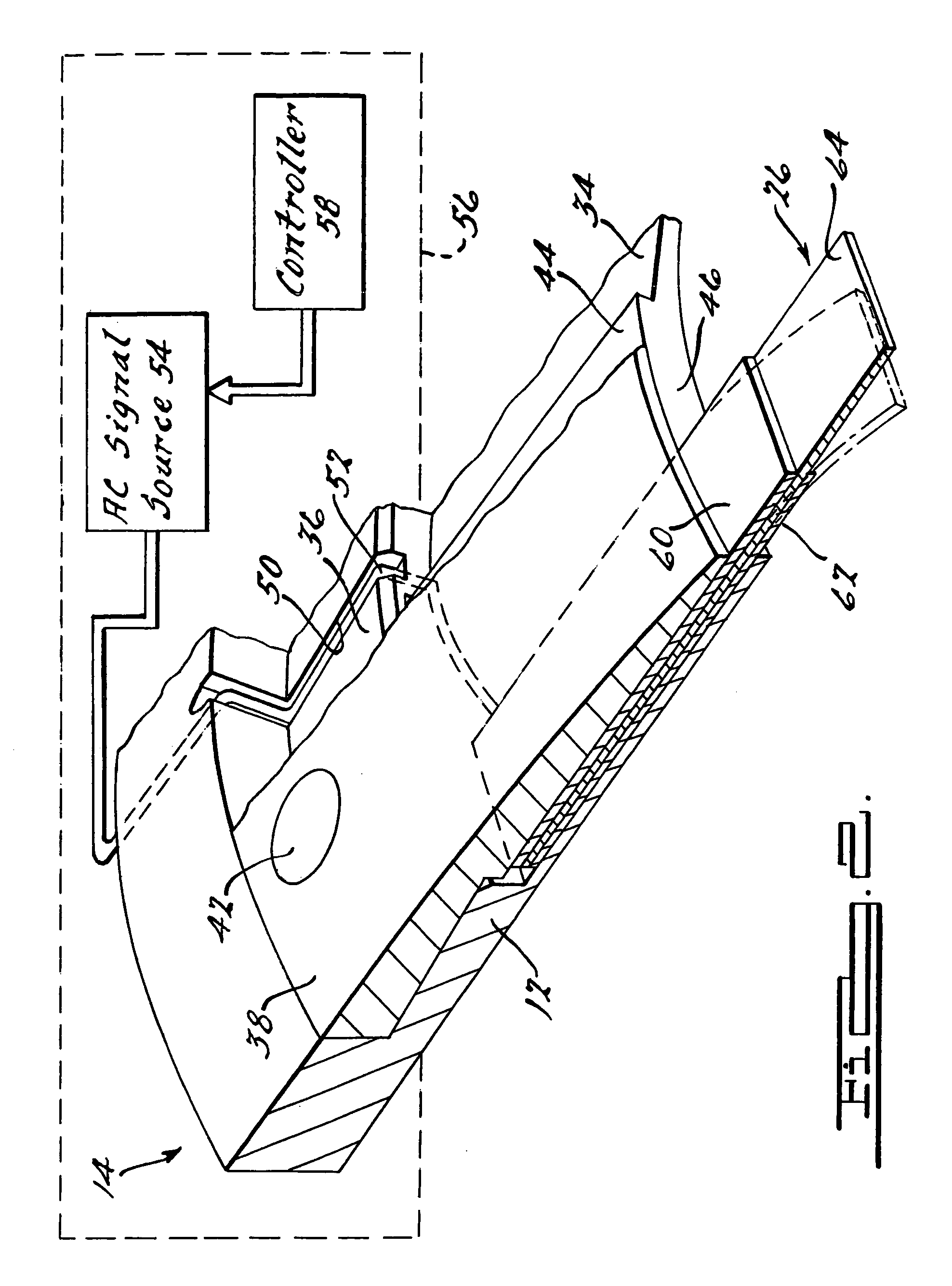
[0016]Referring to FIG. 1, there is shown a noise reduction system 10 formed at a lip portion 12 of a secondary exhaust nozzle 16 of a nacelle 14. The nacelle 14 houses a jet engine 18 and also may or may not include a plug 22, which protrudes from a primary exhaust nozzle 20. The nacelle 14, in this example, is coupled to an undersurface of a wing 24 of an aircraft. It will be appreciated immediately, however, that the point of attachment of the nacelle 14 to the aircraft is not germane to the functioning of the noise reduction system 10 and that the noise reduction system can be employed with nacelles that are attached at other areas of an aircraft, such as along an aft portion of the fuselage.

[0017]Also, while the noise reduction system 10 is shown on the lip portion 12 of the secondary exhaust nozzle 16, it will b...


PUM


Abstract

A noise reduction system for use with an exhaust nozzle associated with a jet engine of an aircraft. The noise reduction system employs a plurality of flow-altering components disposed circumferentially about a lip portion of an exhaust nozzle. In one preferred form the flow-altering components each comprise piezoelectric transduction layers. The flow-altering components are caused to move in an oscillating manner by an AC signal applied thereto such that they move into and out of the exhaust gas emitted from the exhaust nozzle to achieve a desired degree of intermixing of the exhaust flow with the flow adjacent the exhaust nozzle. This produces a reduction in the noise generated by the jet engine. The noise reduction can be utilized during takeoff conditions of an aircraft. The flow-altering components are maintained out of the exhaust gas flowpath during cruise conditions of the aircraft so as not to cause a reduction of thrust, that would in turn result in an increase in the fuel burn during cruise conditions.

Description

FIELD OF THE INVENTION[0001]The present invention relates to noise reduction systems for jet engines, and more particularly to a noise reduction system having a plurality of deployable flow-altering components which can be deployed at selected times of operation of a jet engine to thereby reduce the noise generated by the engine.BACKGROUND OF THE INVENTION[0002]With ever increasingly stringent noise reduction requirements at airports, noise reduction systems for use with jet engines on private and commercial aircraft are becoming increasingly important. The turbulent mixing of primary-secondary and / or secondary-ambient streams is essentially what produces the broadband jet noise emitted from a jet engine. Takeoff conditions are particularly important since the emitted noise power levels increase with increasing velocity difference between the mixing streams.[0003]Present day noise reduction systems used on commercial aircraft typically involve some form of stationary (i.e., static o...

Claims


Application Information

Patent Timeline
IPC IPC(8): A61F11/06G10K11/16
CPCG10K11/161
Inventor BUTLER, GEORGE W.REED, DAVID H.CALKINS, FREDERICK T.DAVIS, CHRISTOPHER L.MABE, JAMES H.
Owner THE BOEING CO
Why Eureka
Try Eureka