Method and apparatus to eliminate processor core hot spots

a hot spot and processor technology, applied in the field of computer processor chips, can solve problems such as power density increase, power density problem, and unit siz

Inactive Publication Date: 2006-08-01
IBM CORP
View PDF28 Cites 86 Cited by
  • Summary
  • Abstract
  • Description
  • Claims
  • Application Information

AI Technical Summary

Benefits of technology

[0016]A principle object of the present invention is to provide a method of task switching in a symmetric multi-processing (SMP) system that will determine when a heat buildup in a unit of a processor is occurring, and, respondent to that determination will move the task to a different processor in the SMP.

Problems solved by technology

Power density problems are aggravated by the dramatic reduction in size of units in the processor.
Several problems are encountered as areas decrease and power density increases.
Wiring on semiconductor chips is subject to electromigration failure when high current densities are run through the wiring for long periods of time.
Electromigration wearout effects increase exponentially with temperature, further exacerbating problems associated with high power densities.
Even though the buried oxide layer is relatively thin, the low thermal conductance of the layer impedes the heat flow and further contributes to formation of hot spots on an SOI semiconductor chip.
Furthermore, in specific computer programs, particularly numerically intensive computing (NIC), a large iterative sequence can reuse the same set of components such that hot spots are created in the components and subject them to overheating, damage, or accelerated wearout through electromigration or other mechanisms.
One method is to simply have the processor operate at a lower clock frequency, thereby reducing performance.
However, this system adds to manufacturing costs of the processor, and creates significant overhead in activating and deactivating the units of the processor to affect overall performance of the processor.
Even when the ability to deactivate a unit when it is not in use is implemented, the ability to deactivate units, such as the FPMADD, is no help when the processor is making a large iterative use of the FPMADD, perhaps lasting many seconds, many minutes, or even many hours.
However, if the burner is allowed to remain on for more than a short time, damage to the hand will occur.

Method used


Image

  • Method and apparatus to eliminate processor core hot spots
  • Method and apparatus to eliminate processor core hot spots
  • Method and apparatus to eliminate processor core hot spots

Examples


Embodiment Construction

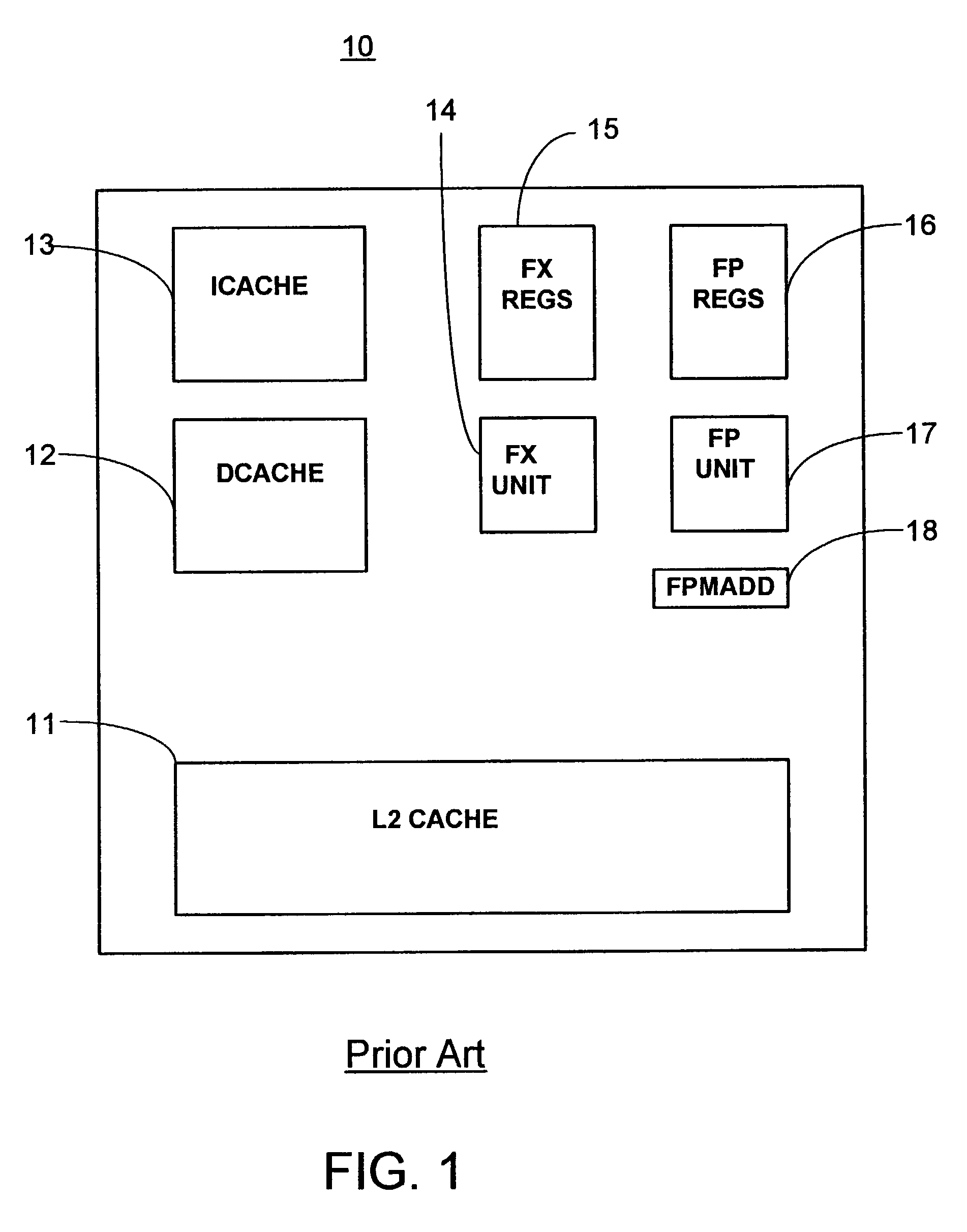
[0036]Having reference now to the figures, and in particular FIG. 1, a processor 10, is shown. Processor 10 can be any processor. Examples of processors include Power4 by the International Business Machines Corporation, or Itanium by the Intel Corporation. Some of the major functional units commonly found on such processors are shown.

[0037]L2 cache 11 is one memory in a memory hierarchy common in modern processors. L2 cache 11 is commonly in the range of one megabyte (1 MB) to 16 MB, but could be of any size. L2 cache is often optimized for bandwidth, rather than for speed or density.

[0038]Icache 13 and dcache 12 represent a common implementation of the “first level cache” L1 cache in the memory hierarchy. Dcache 12 holds data that is likely to be used in the processor; icache 13 holds instructions that are likely to be used in the processor. Typical sizes for icache 13 and dcache 12 are 32,000 bytes (32 KB) to 256 KB, although larger and smaller sizes are possible. Icache 13 and dc...


PUM

PropertyMeasurementUnit
temperatureaaaaaaaaaa
power densityaaaaaaaaaa
data affinityaaaaaaaaaa

Abstract

Methods and apparatus are provided for eliminating hot spots on processor chips in a symmetric multiprocessor (SMP) computer system. Some operations, in particular, floating point multiply/add, repetitively utilize portions of a processor chip to the point that the average power of the affected portions exceeds cooling capabilities. The localized temperature of the affected portions can then exceed design limits. The current invention determines when a hot spot occurs and task swaps the task to another processor prior to the localized temperature becoming too hot. Moving of tasks to processors that have data affinity with the processor reporting a hot spot is considered. Further considerations include prioritizing unused processors and those processors that have not recently reported a hot spot.

Description

FIELD OF THE INVENTION[0001]The present invention relates to computer processor chips. More specifically, the present invention relates to symmetric multiprocessor (SMP) computer systems in which localized areas on the computer chips become overheated due to a large amount of uninterrupted processing activity in the localized area.DESCRIPTION OF THE RELATED ART[0002]Power dissipation and power density are increasingly becoming a concern in both computer systems and computer processor design. The components of the processor, such as the logic gate transistors, buses, and registers generate heat during switching activity, as capacitance of transistor gate electrodes and wiring capacitance is charged and discharged at high frequency.[0003]A first-order approximation of power dissipation is expressed in equation (1) below:P=½*C*V2*f  (1)[0004]Where P is power in watts; C is capacitance in farads; V is voltage in volts; and f is frequency in Hertz. Equation (1) assumes a single switch fo...

Claims


Application Information

Patent Timeline
Patent Type & Authority Patents(United States)
IPC IPC(8): G06F9/46G01K15/00G06F11/00G06F15/00G06F13/24H02H5/04G06F1/20G06F9/00G06F9/48
CPCG06F1/206G06F9/4881G06F9/5094Y02B60/142G06F2209/5014Y02D10/00
Inventor LUICK, DAVID ARNOLD
Owner IBM CORP
Why Eureka
Try Eureka