Spring-suspension magnetically stabilized pick-up arm

a magnetically stabilized, spring-suspension technology, applied in mechanical recording, optical recording/reproducing, instruments, etc., can solve the problems of inability to reduce the disturbance of the pick-up arm movement to a system immanent minimum, detrimental to the fidelity of the cartridge's performance, and affecting the undisturbed tracking of the groove modulation

Inactive Publication Date: 2006-08-01
SCHRODER FRANK
View PDF7 Cites 6 Cited by
  • Summary
  • Abstract
  • Description
  • Claims
  • Application Information

AI Technical Summary

Benefits of technology

[0017]According to the invention, the torsion element facilitates three degrees of freedom(of movement). The pick-up arm receiving element and therefore the pick-up arm tube is suspended by a vertical thread which, to allow for rotation in the horizontal plane, needs to be slightly twisted only. When the arm is moved up and down, the thread is just being bent at the lower end(inside the pick-up arm tube receiving element) where it exits the magnet / pole piece. Rotation of the armwand around it's longitudinal axis is prevented since the center of gravity of the counterweight / pick-up arm tube / cartridge assembly is located below the vertical bearing(thread bending) point. This results in a steady condition in regard to the longitudinal axis of the pick-up arm tube.
[0018]While coupling the pick-up arm tube receiving element to the pick-up arm chassis without slack(or bearing play) the high inherent damping of the torsion element surpresses the excitement of mechanical resonances in the pick-up arm chassis by the cartridge. The length of the torsion element (between the upper fixing and the lower exit point) also ensures the suppression of footfall induced pick-up arm chassis vibrations relayed to the pick-up arm tube, meaning, parasitic vibrations are not added to the original signal(as encoded in the groove's modulation), maintaining it's fidelity.
[0021]The permanent magnets in the pick-up arm tube and the pick-up arm chassis serve the function of stabilizers and dampers in all dimensions, including sideways, back and forth, or up and down. Additionally, the torsion element strongly inhibits the excitement / occurrence of pick-up arm tube resonances resulting from footfall or airborne resonances. Furthermore, the distance between the magnet in the pick-up arm wand and the perpendicular, pick-up arm chassis mounted counterpart is variable and facilitates the adjustment of the rigidity and the damping properties of this “quasi”-rigid bearing.
[0023]This hole, effectively a well, can be filled with silicon oil. This yields the advantage of immersing the torsion element in silicon oil for approximately one third of it's length, additionally damping the transmission of vibrations stemming from the pick-up arm chassis via the torsion element to the pick-up arm tube. The dimensions of this “oil well” and the choice of silicon fluid of suitable viscosity exclude the possibility of overdamping the pick-up arm / cartridge resonance. Since the torsion element is running vertically through the “oil well”, the silicon oil has a neglectable amount of damping in the horizontal plane regards to horizontal pick-up arm tube movement.
[0024]Optionally the pick-up arm receiving element and tube can be made out of a single piece of wood or a sandwich of several woods, the woods are characterized by high bending strength combined with high internal damping. Particularly suitable are ebony, jacaranda, acacia, cocobolo and bamboo, and many others are suitable too. The inner diameter or bore hole of the pick-up arm tube is chosen to be just large enough to take up the pick-up arm wiring, preventing microphony effects and the excitement of the enclosed column of air (pipe resonances).

Problems solved by technology

One of the drawbacks of these bearing principles is that the inherent friction and therefore disturbances of the pick-up arm movement can only be reduced to a system immanent minimum.
The disturbances are the consequence of a continuous alternation between static friction and sliding / rolling friction(“stick-slip” or “stiction” effect) while the pick-up arm is traversing the record forcing the cartridge to move in a jerky fashion, this being a detrimental influence on the fidelity of the cartridge's performance.
Additionally, the use of a bearing that rigidly couples the pick-up arm tube to the turntable (pick-up arm base, plinth, motor, platter) negatively affects the undisturbed tracking of the groove modulation.
The option to dampen the so-called “tonearm-cartridge resonance” (typically between 7 Hz and 14 Hz) by means of a silicon oil damping trough and pin / paddle featured by many pick-up arms negatively affects the reproduction of the upper frequency range of the music signal, overdamping.
Another drawback of conventional pivoted pick-up arms is their sensitivity to shock-induced damage.
Commonly used bearing cups made out of precious or semi-precious stone are very brittle and crack or break easily.
Their counterparts, bearing pins or cones—as much as conventional ball bearings almost inescapably suffer some damage after exposure to a strong shock or unsuitably rough handling.
The damage manifests itself in flattened or bent bearing pin tips, flat spots on balls, indentations on their counterpart ballraces, these damages leading to increased and uneven friction, substantially reducing the fidelity of the pick-up arm.
The drawbacks of such an arrangement are: a) the sickle-shaped element increases the effective mass, b) the sickle-shaped element is prone to resonances, it is effectively a resonating tongue, and c) the arm “sees” no damping of vibrations in the vertical plane, stemming from i.e. warped records or footfall.
It's disadvantage is that tilting motions and resonances along the pick-up arm's vertical axis are damped by the viscous fluid exclusively.
The disadvantage of such arrangement lies in the fact that the pick-up arm still features a conventional pivot for the vertical movement of the armtube displaying a certain frictional resistance in operation.
Any change of the position of the pick-up arm tube results in an alteration of the flux line geometry of the magnetic field surrounding the two magnets.
Since the torsion element is running vertically through the “oil well”, the silicon oil has a neglectable amount of damping in the horizontal plane regards to horizontal pick-up arm tube movement.

Method used


Image

  • Spring-suspension magnetically stabilized pick-up arm
  • Spring-suspension magnetically stabilized pick-up arm
  • Spring-suspension magnetically stabilized pick-up arm

Examples


Embodiment Construction

OF THE INVENTION

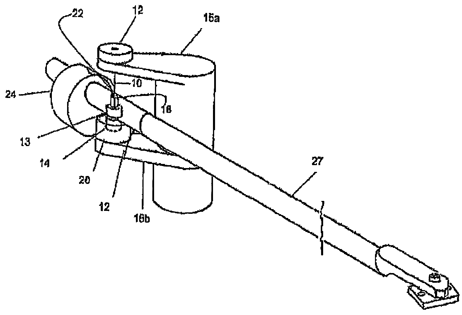
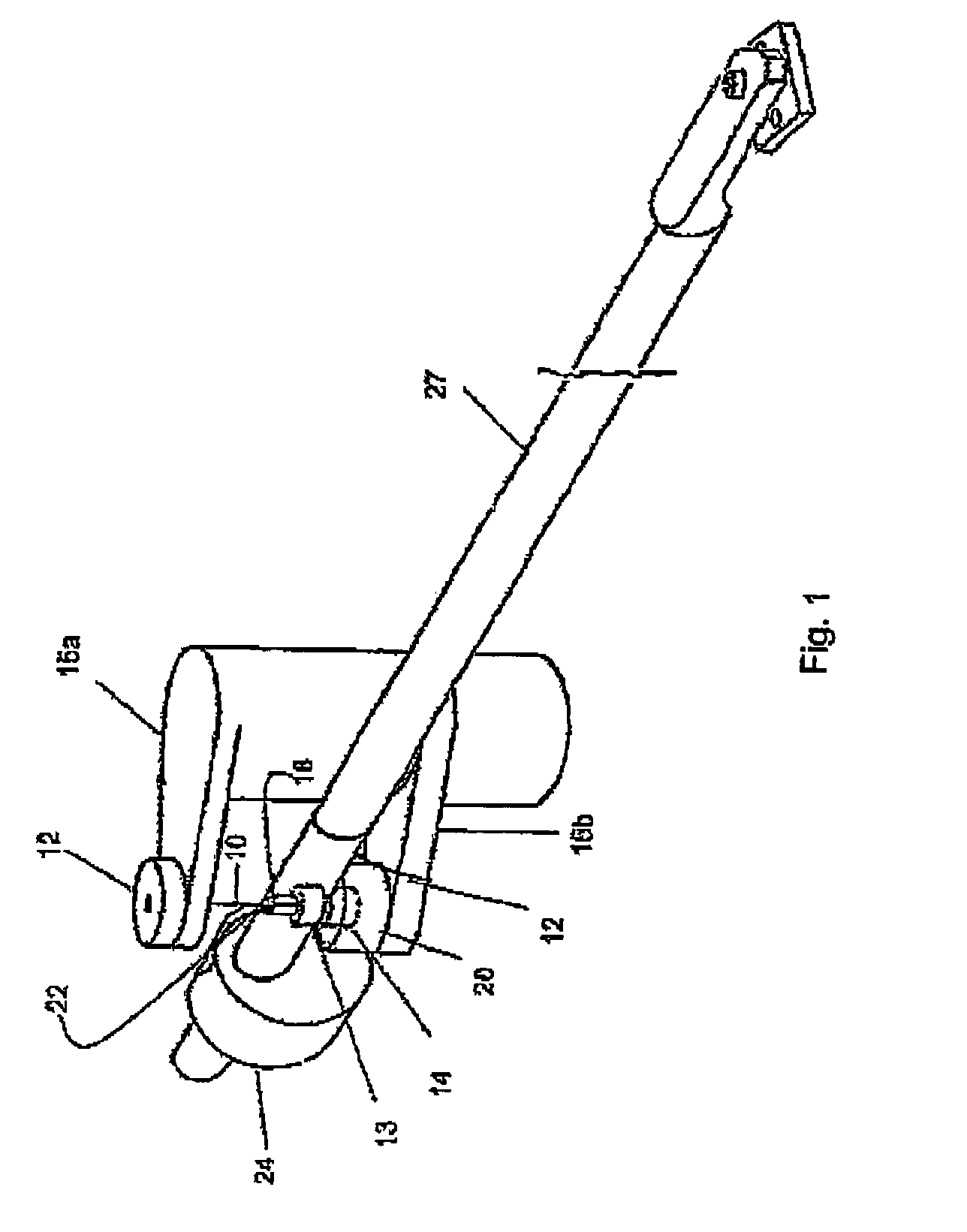
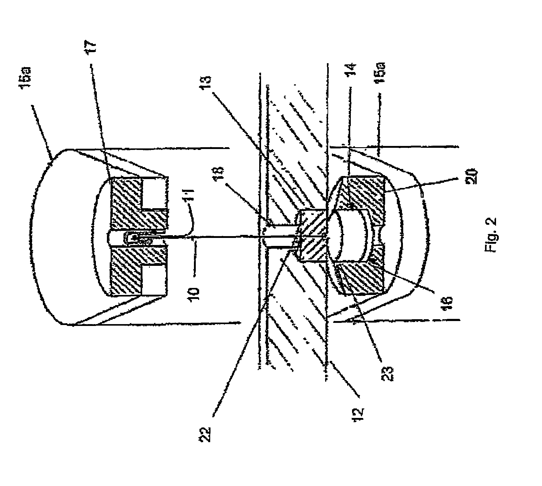
[0029]FIG. 1 shows a schematic side view of the complete pick-up arm system. Along it's vertical axis of rotation the pick-up arm receiving element 12 having an arm wand or pick-up arm tube 21 press-fit into or otherwise held by it. The receiving element 12 features a (sack-, drill-) hole or bore 18 through which the torsion element 10 is running. Following axially is hole 22, running through the permanent magnet 13, said hole's 22 diameter equal to the diameter of the torsion element, therefore much smaller than the diameter of hole 18. The hole / bore 18 can be filled partially or entirely with silicon oil to dampen resonances within the torsion element. The diameter of hole 22 does not permit any leakage of silicon oil.

[0030]At it's lower end the torsion element 10 is centered, free of play / slack, by the lower, drilled(hole 22) permanent magnet, fixed / held by a knot 23, or glued in. A gap exists between the permanent magnet 13, set into the pick-up arm receiving ele...


PUM

PropertyMeasurementUnit
frequencyaaaaaaaaaa
frequencyaaaaaaaaaa
polarityaaaaaaaaaa

Abstract

The invention relates to a pick-up arm system for the reproduction or replay of records comprising a pick-up arm chassis and a pick-up arm tube. The torsion element suspension of the pick-up arm is axially stabilized by means of cylindrical permanent magnets which are arranged in a vertical direction and have opposite polarities, said elements forming a rotating bearing or a pivot. According to the invention, the torsion element runs in a congruent manner with respect to the vertical axis of rotation through the horizontal point of rotation of the receiving element for the tube of the pick-up arm. The lower part of the torsion element is connected to a permanent magnet which is connected to the receiving element for the pick-up arm or tube and the upper part of the torsion element is fixated attached to the upper chassis of the pick-up arm. A second permanent magnet or otherwise attached of opposite polarity is fixated in the lower chassis of the pick-up arm in a perpendicular position below said permanent magnet.

Description

FIELD OF THE INVENTION[0001]The invention relates to a pick-up arm system for the reproduction or replay of records comprising a pick-up arm chassis and a pick-up arm tube, whereby a torsion element suspension of the pick-up arm tube is axially stabilized by means of cylindrical magnets of opposite polarity, forming a rotating bearing.BACKGROUND OF THE INVENTION[0002]For conventional pivoted pick-up arms the current state of technology mandates the use of knife edge-, ball-, ball and cone-, unipivot bearings or a combination of any of these. One of the drawbacks of these bearing principles is that the inherent friction and therefore disturbances of the pick-up arm movement can only be reduced to a system immanent minimum. The disturbances are the consequence of a continuous alternation between static friction and sliding / rolling friction(“stick-slip” or “stiction” effect) while the pick-up arm is traversing the record forcing the cartridge to move in a jerky fashion, this being a de...

Claims


Application Information

Patent Timeline
Patent Type & Authority Patents(United States)
IPC IPC(8): G11B7/085G11B3/12
CPCG11B3/125
Inventor SCHRODER, FRANK
Owner SCHRODER FRANK
Why Eureka
Try Eureka