Method of estimating the fuel/air ratio in a cylinder of an internal-combustion engine

a technology of internal combustion engine and fuel/air ratio, which is applied in the direction of machines/engines, electrical control, instruments, etc., can solve problems such as insufficient robustness, and achieve the effect of more robustness

a technology of internal combustion engine and fuel/air ratio, which is applied in the direction of machines/engines, electrical control, instruments, etc., can solve problems such as insufficient robustness, and achieve the effect of more robustness

US7086391B2Inactive Publication Date: 2006-08-08INST FR DU PETROLE

Image

  • Method of estimating the fuel/air ratio in a cylinder of an internal-combustion engine
  • Method of estimating the fuel/air ratio in a cylinder of an internal-combustion engine
  • Method of estimating the fuel/air ratio in a cylinder of an internal-combustion engine

Examples


Embodiment Construction

[0030]The advantages of a fuel / air ratio estimation in each cylinder individually are numerous in relation to an average fuel / air ratio estimation for all of the cylinders:[0031]cost price gain if the estimation is performed from a single fuel / air ratio probe at the turbine outlet,[0032]emissions reduction by finer fuel / air ratio adjustment in each cylinder,[0033]improved driveability (delivered torque regulation),[0034]fuel consumption reduction through cylinder harmonization,[0035]injection system diagnosis (detection and compensation of the drift of a cylinder or of the failure of the injection system),[0036]correction of the air and / or burnt gas filling disparities.

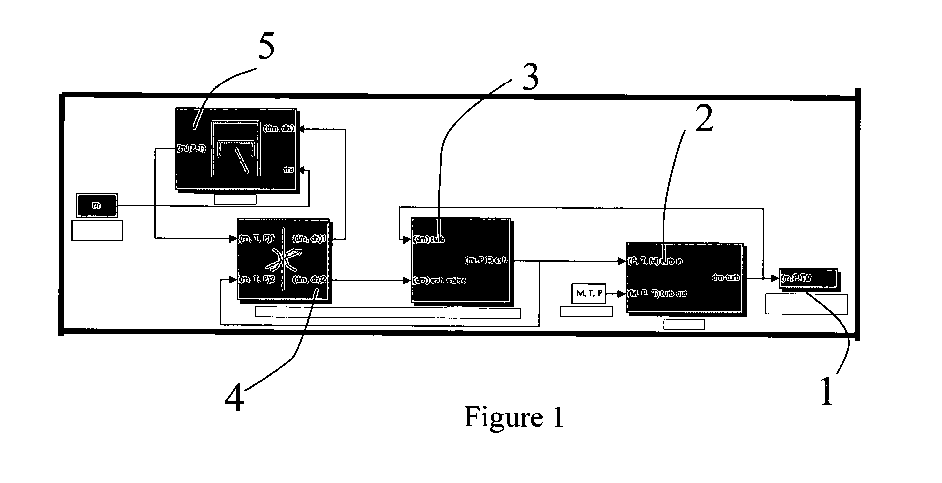
[0037]Description of the Exhaust Process

[0038]The exhaust process comprises the path travelled by the gases from the exhaust valve to the atmosphere, at the exhaust muffler outlet. The engine in the present embodiment example is a 2000-cm3 4-cylinder engine. It is equipped with a turbo or supercharger whose action can...


PUM


Abstract

The present invention relates to a method of estimating the fuel / air ratio in each cylinder of a multicylinder internal-combustion engine comprising an exhaust circuit in which a single detector measures the fuel / air ratio of the exhaust gas. The estimator comprises a physical model (RTM) representing the expulsion of the gases from the cylinders and the travel thereof in the exhaust circuit to the detector, the model being coupled with a non-linear state observer of Extended Kalman Filter (KF) type.

Description

BACKGROUND OF THE INVENTION[0001]1. Field of the Invention[0002]The present invention relates to a method of estimating the fuel / air ratio for each cylinder of an internal-combustion engine, in particular an injection engine.[0003]2. Description of the Prior Art[0004]Knowledge of the fuel / air ratio, characterized by the mass of fuel to the mass of air, is important for all vehicles, whether equipped with gasoline or diesel engines. In the case of a gasoline engine, the fuel / air ratio influences the nature of the emissions. A slightly rich mixture creates an increase in the CO and HC emissions, whereas a slightly lean mixture increases the NOx emissions. It is therefore of great importance to precisely control the fuel / air mixture cylinder by cylinder in this type of engine running with a total engine fuel / air mixture (average of the 4 cylinders) around stoichiometry so as to limit the emissions. In the case of conventional diesel engines or of gasoline engines running under stratifi...

Claims


Application Information

Patent Timeline
08 Aug 2006
Publication
US7086391B2
IPC
F02D41/14; B60T7/12; F02D45/00; F02D41/36; F02D41/40
CPC
F02D41/1401; F02D41/1458; F02D41/1474; F02D41/1454; F02D41/1405; F02D2041/1417; A23B4/056; A47J36/2488
Inventors
MOULIN, PHILIPPE; CORDE, GILLES