MRI tunable antenna and system

a tunable antenna and antenna technology, applied in the field of mri tunable antennas and systems, can solve the problems of less effective circuitry, less manageable signal coupling effects, and increased signal coupling effects, so as to minimize external em coupling or interactions, the effect of minimizing em from the environmen

Inactive Publication Date: 2006-08-08
THE JOHN HOPKINS UNIV SCHOOL OF MEDICINE
View PDF31 Cites 93 Cited by
  • Summary
  • Abstract
  • Description
  • Claims
  • Application Information

AI Technical Summary

Benefits of technology

[0017]The detection device includes a strip array antenna including at least one, and preferably a plurality of conductors being arranged so as to be generally parallel to each other and a plurality of reactive components or elements, such reactive components or elements including for example a capacitor, an inductor or both. At least one of the plurality of reactive components is electrically coupled to each conductor and to one of ground or a virtual ground. Each of the conductors has a length and each of the reactive components has a value set so that the combination of the conductor length and the reactance of the reactive component is such as to substantially reduce the coupling of a signal in one of the conductors to an adjacent conductor.
[0018]More particularly, the reactance value of the reactive component value is set or tuned so that the effective electrical length of each conductor is substantially equal to be about nλ / 4, where n is an integer ≧1 and λ is the EM wavelength of the signal to be detected by each conductor in combination with the at least one reactive component. For MRI applications, λ is the wavelength corresponding to the NMR frequency for the nuclei being subjected to a given magnetic field strength by the main or primary magnetic coils. For example, the quarter wavelength for a proton NMR in a 1.5 Telsa magnetic field in air is about 117 cm, which reduces to about 46 cm in a glass dielectric PSA (see Lee et al, Magn Reson Med 2001; 45: 673–683), and is effectively reduced and / or adjusted further in the conductor strips of the present invention through the use of the reactive components.
[0019]In a more particular embodiment, the length of each conductor also is established so as to optimize the NMR performance of the array for the particular geometry and size of the sample, sub-region of the sample, region of interest or organ to be imaged and the strip array antenna is configured and arranged so as to substantially reduce coupling of signals between adjacent conductors. In this way, the conductor length is set so NMR performance is optimized for the region of interest through the use of the reactive component, whose values are set such as to tune the chosen length of the conductor so as to be electrically equal to about nλ / 4, to thereby substantially reduce signal coupling. Thus, and in an exemplary embodiment, the length of the conductor can be reduced so as to be on the order of from about 10 to 30 cm, dimensions that are comparable to the body or depth of specific organs of interest, while the reactance of the reactive components is used to tune the length of each conductor so as to be electrically equal to about nλ / 4.
[0020]In another more particular embodiment, the length of each conductor is established so as to optimize the signal-to-noise ratio (SNR) over a desired range in an area or region of interest, and the strip array antenna also is configured and arranged so as to substantially reduce coupling of signals between adjacent conductors. In this way, the conductor length can be set so the SNR is optimized for the region of interest through the use of the reactive component(s), whose values are set such as to tune the length of the conductor so as to be electrically equal to about nλ / 4 with a geometry configured to substantially reduce signal coupling.
[0034]In yet another embodiment, the detection device is configurable so as to include a conducting electromagnetic (EM) interference guard that is electrical connected in a fashion so that the guard substantially electrically isolates at least a portion of each conductor (e.g., the ends of the conductors) from the environment including areas of the imaged object outside of the specific area being scanned and other conducting surfaces that may be present. In one embodiment, the EM guard includes two conducting guard strips, each guard strip being disposed proximal the ends of each conductor and insulated from the tuned conductors that form the detector elements, so as to minimize EM from the environment. In a more specific embodiment, a long axis for each of the guard strips extends generally perpendicular to a long axis of each conductor.
[0035]In another embodiment, a plurality of guard strips are arranged about the periphery of the plurality of conductors that form the detector elements so as to, in effect enclose both the ends and sides of the plurality of conductors. In yet another embodiment, the EM guard comprises one or more members that are configured so as to provide any of a number of geometrical shapes such as circular and oval. These one or more members are formed about the ends or about the periphery of the plurality of conductors such that the configuration minimizes external EM coupling or interactions.

Problems solved by technology

Although overlapping adjacent coil(s) and using low impedance pre-amplifiers have been effective in minimizing decoupling artifacts and SNR degradation, such circuitry becomes less effective as the number of coils and / or the coil density is increased.
In particular, as the spacing between adjacent coils and between adjacent portions of a coil is decreased signal coupling effects increase and become less manageable by the various measures deployed to counter such effects.
Because the spatial resolution depends in part on the number of repetitions and therefore the number of phase-encoding steps, and because the repetition rate is limited by the MR relaxation times; a higher resolution image generally takes a longer time.
A problem with all of these methods (SMASH, SENSE, ASP, etc.) is that conventional MRI phased array coils are limited in the number of coils that can be deployed, by the limitations imposed by both their loop structure and the de-coupling requirements for the mutual induction between the elements.
Because the number of coils in the phased array correlates to the maximum factor for reducing the number of phase encoding steps, existing phased array designs significantly limit the potential for parallel spatial encoding.

Method used


Image

  • MRI tunable antenna and system
  • MRI tunable antenna and system
  • MRI tunable antenna and system

Examples


Embodiment Construction

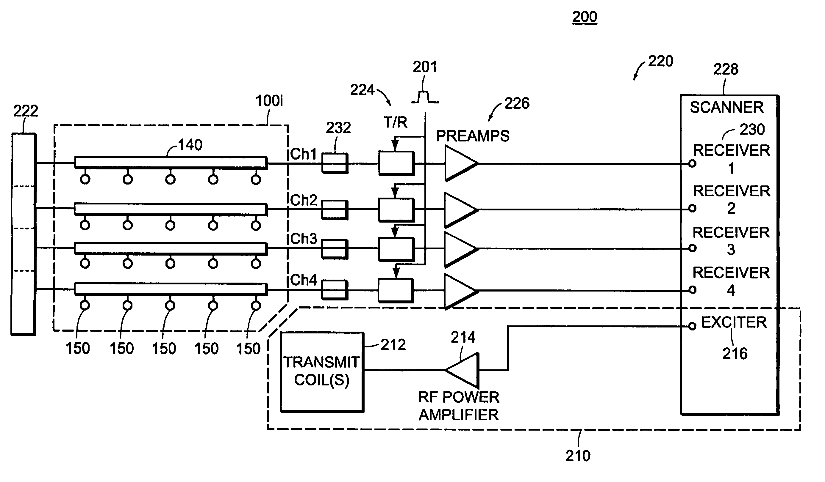
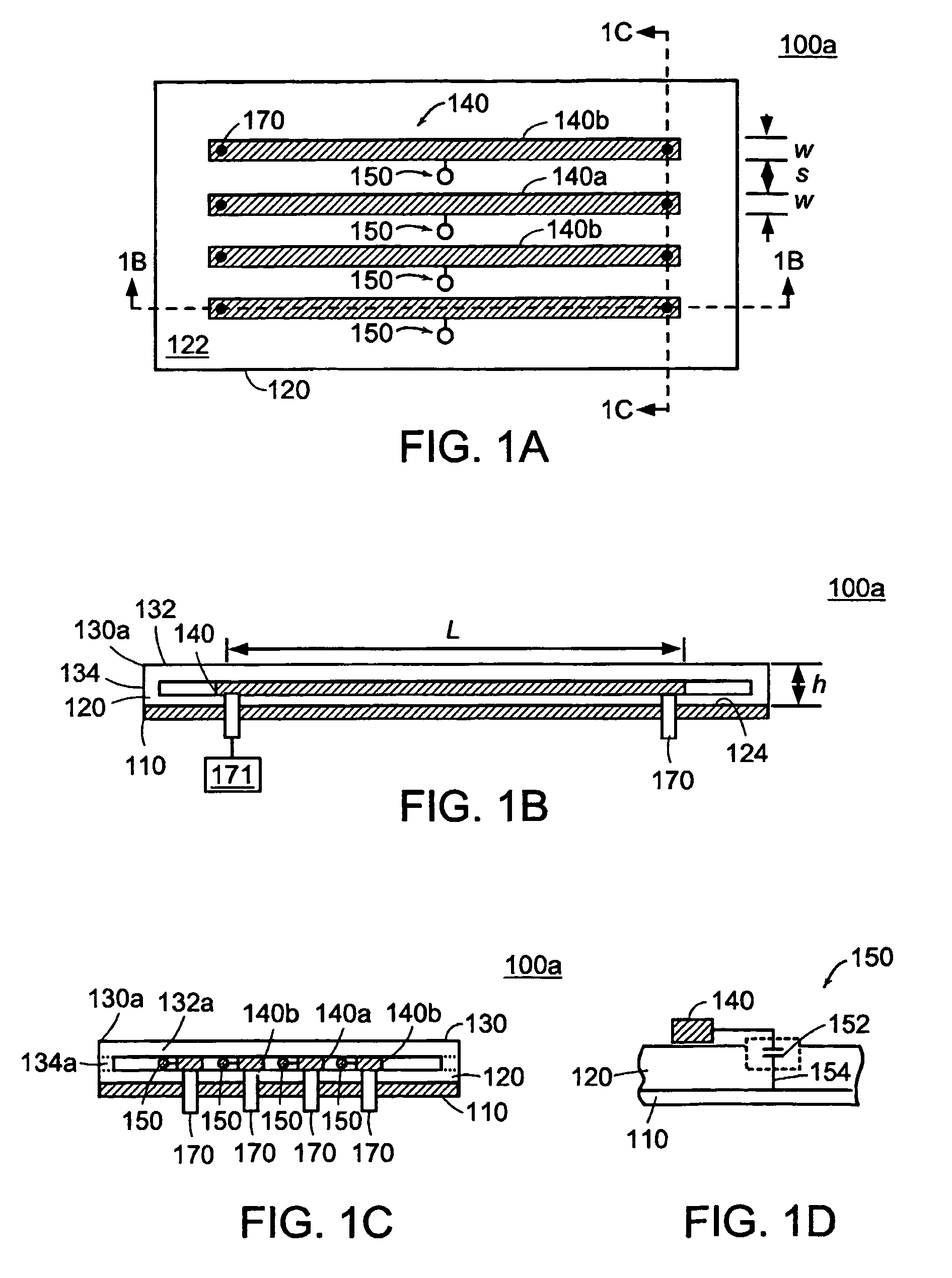
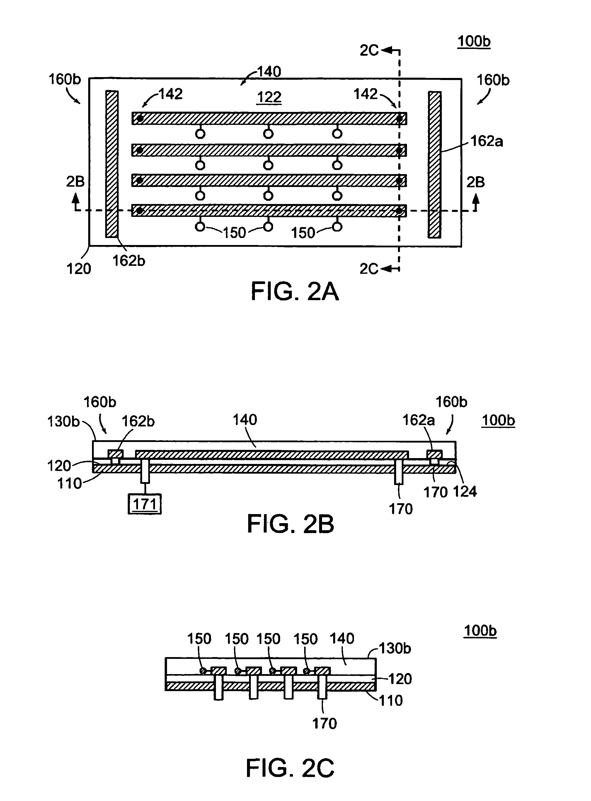
[0077]Referring now to the various figures of the drawing wherein like reference characters refer to like parts, there are shown in FIGS. 1–8 various views of near-field RF strip array antennas 100a–h according to the present invention. Such strip array antennas can be configured and arranged so as to form a strip array antenna that is planar, arcuate / curved or cylindrical in form. These illustrative forms of a strip array antennas 100a–h shall not be limiting, as the strip array antenna of the present invention can be configured or arrayed so as to form a strip array antenna having any geometric shapes or configuration. In the following, reference numerals 100, 130, 140 and 150 are used when generally referring respectively to a strip array antenna according to the present invention, to the overlay thereof, to any or all of the conductor strips thereof and to the reactive / tuning elements thereof. When reference is being made to a specific antenna embodiment, to a specific conductor...


PUM


Abstract

A strip array antenna including a number of conductors (14) that are connected to ground or virtual ground though at least one reactive component (150). The apparent electrical length of conductors (140) is tuned so that it equals an integer multiple of a quarter wavelength at the operating frequency.

Description

[0001]This application also claims the benefit of U.S. Provisional Application Ser. No. 60 / 345,917 filed Dec. 31, 2001, the teaching of which are incorporated herein by reference.FIELD OF INVENTION[0002]The present invention generally relates to apparatus and methods for nuclear magnetic resonance (NMR), magnetic resonance (MR) imaging (MRI), and magnetic resonance spectroscopy (MRS). More particularly the present invention relates to an apparatus having a tunable near-field radio-frequency strip array antenna that can be used for conventional NMR, conventional spatially encoded MRI or MRS and parallel spatial encoded MRI. The present invention also relates to methods and NMR, MRI or MRS systems related thereto.BACKGROUND OF THE INVENTION[0003]Magnetic resonance imaging (MRI) is a technique that is capable of providing three-dimensional imaging of an object. A conventional MRI system typically includes a main or primary magnet that provides the main static magnetic field Bo, magneti...

Claims


Application Information

Patent Timeline
Patent Type & Authority Patents(United States)
IPC IPC(8): G01V3/00G01R33/34G01R33/3415
CPCG01R33/3415G01R33/34046G01R33/34007
Inventor BOTTOMLEY, PAUL
Owner THE JOHN HOPKINS UNIV SCHOOL OF MEDICINE
Why Eureka
Try Eureka