Apparatus for cleaning channels for air conditioning and other purposes

a technology for air conditioning and apparatus, applied in the direction of dirt cleaning, hollow article cleaning, combustion treatment, etc., can solve the problems of affecting the cleaning effect of the size and thereby weight of the electric motor become too large to allow sensible movement, and the sparking of the electric motor inside the space to be cleaned constitutes a severe risk of fire and explosion

Inactive Publication Date: 2006-08-15
LIFA IAQ
View PDF15 Cites 1 Cited by
  • Summary
  • Abstract
  • Description
  • Claims
  • Application Information

AI Technical Summary

Benefits of technology

[0014]The problems related to fire safety and electrical security hampering electrical drives are avoided thanks to the hydraulic drive. In addition, the motor connected to the brush can be designed much lighter and more compact.
[0015]Compared to a pneumatic solution, the use of a sizable, costly, noisy and awkwardly operated compressor is avoided. In addition, oiling of the duct system to be cleaned is eliminated, because a hydraulic system can in practice be constructed fully liquid tight. Possible risks of leakage may be minimized by using a biodegradable hydraulic oil and by providing any parts which are leakage-prone with leak protection such as thermocontractible protective sleeves.
[0017]Due to the receiver unit, an improved cleaning result and enhanced dirt removal are achieved. The receiver unit cannot be broken even by collisions of large particles of dirt.

Problems solved by technology

The prior art is hampered by several drawbacks.
Particularly when extensive air conditioning systems are being cleaned, the cleaning efficiency required is so high that the motor size and thereby weight of electric motor drives become too extensive to allow sensible movement of the motor on the guide wire cable.
As the space to be cleaned is in practice filled by a mixture of dust and air, sparking of the electric motor inside the space to be cleaned constitutes a severe risk of fire and explosion.
In addition, the duct system, which usually is made of an electrically conductive material, is problematic in combination with electric drives, as the electric lines inside the guide wire cable may in the case of a damaged wire cable short circuit in the duct system being cleaned, whereby there is not only a risk of fire and explosion but also of electric shock.
Pneumatic drives arc also hampered by several drawbacks.
Such large compressors are either driven by combustion motors or alternatively, they require three-phase current which is not available in all real properties.
Pneumatic compressors and motors are relatively loud and the pneumatic hoses required by the system are awkwardly moved inside the buildings.
Solutions based on a mechanical flexible shaft for their part are extremely heavy at the power levels required, and furthermore, the guide wire cable will easily be too loose to be inserted into the duct by pushing.
Hereby the resulting friction is also excessive for the motor and transmission.
The prior art is further hampered by the aftertreatment of the dirt removed from the duct system.
If the outlet air is prefiltered, some larger solid particle may break the filter system used at present, because the intense underpressure exerts intense suction moving all sizes of dirt particles toward the filter at high speeds.
If, then, no filtration is performed, substances which are detrimental to health may spread into the environment.
The prior art is limited to the cleaning of air-conditioning ducts only and offers no means for cleaning planar surfaces or for treating such surfaces without dust nuisance.
If the surface to be treated contains health-endangering substances, use of the prior art equipment may cause health detriments unless the workers protect themselves in the required fashion.

Method used


Image

  • Apparatus for cleaning channels for air conditioning and other purposes
  • Apparatus for cleaning channels for air conditioning and other purposes
  • Apparatus for cleaning channels for air conditioning and other purposes

Examples


Embodiment Construction

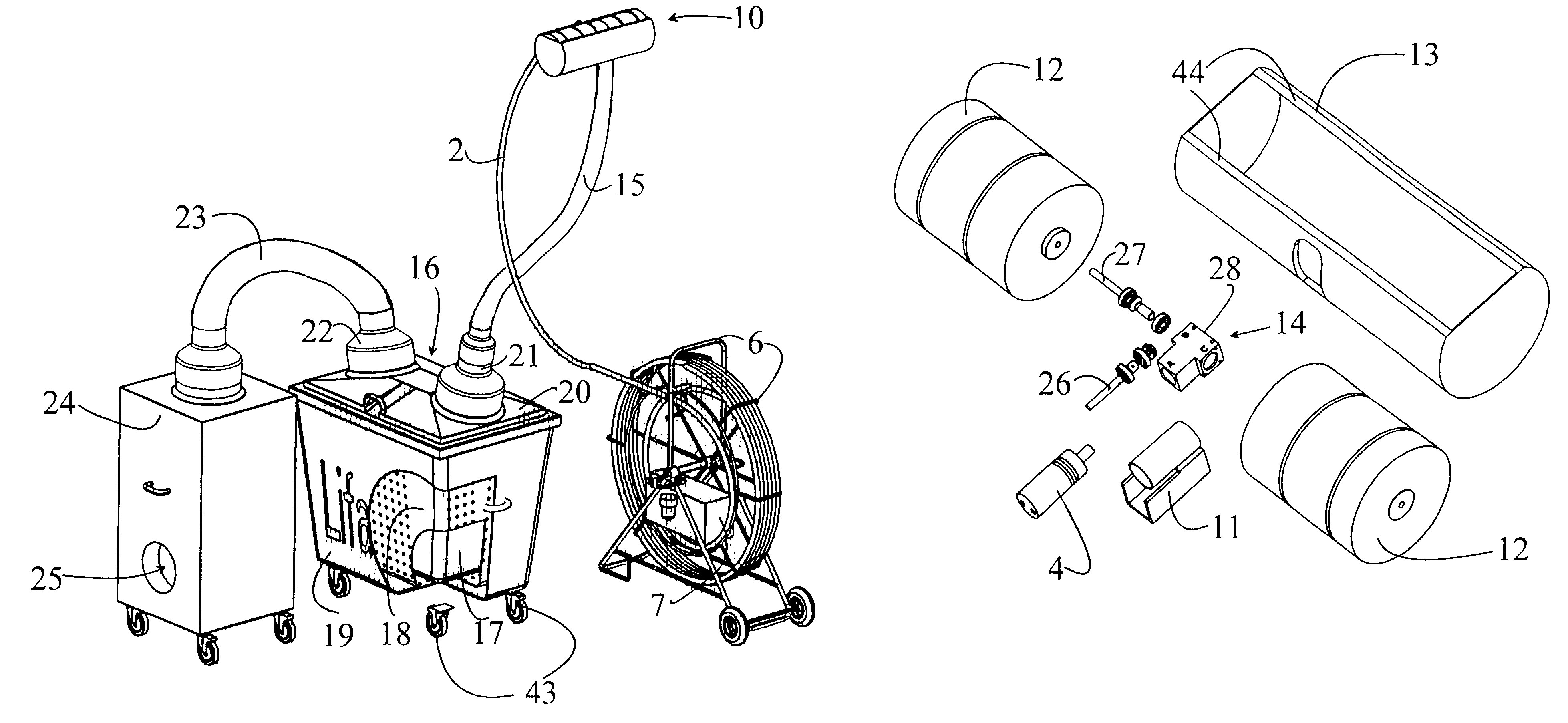
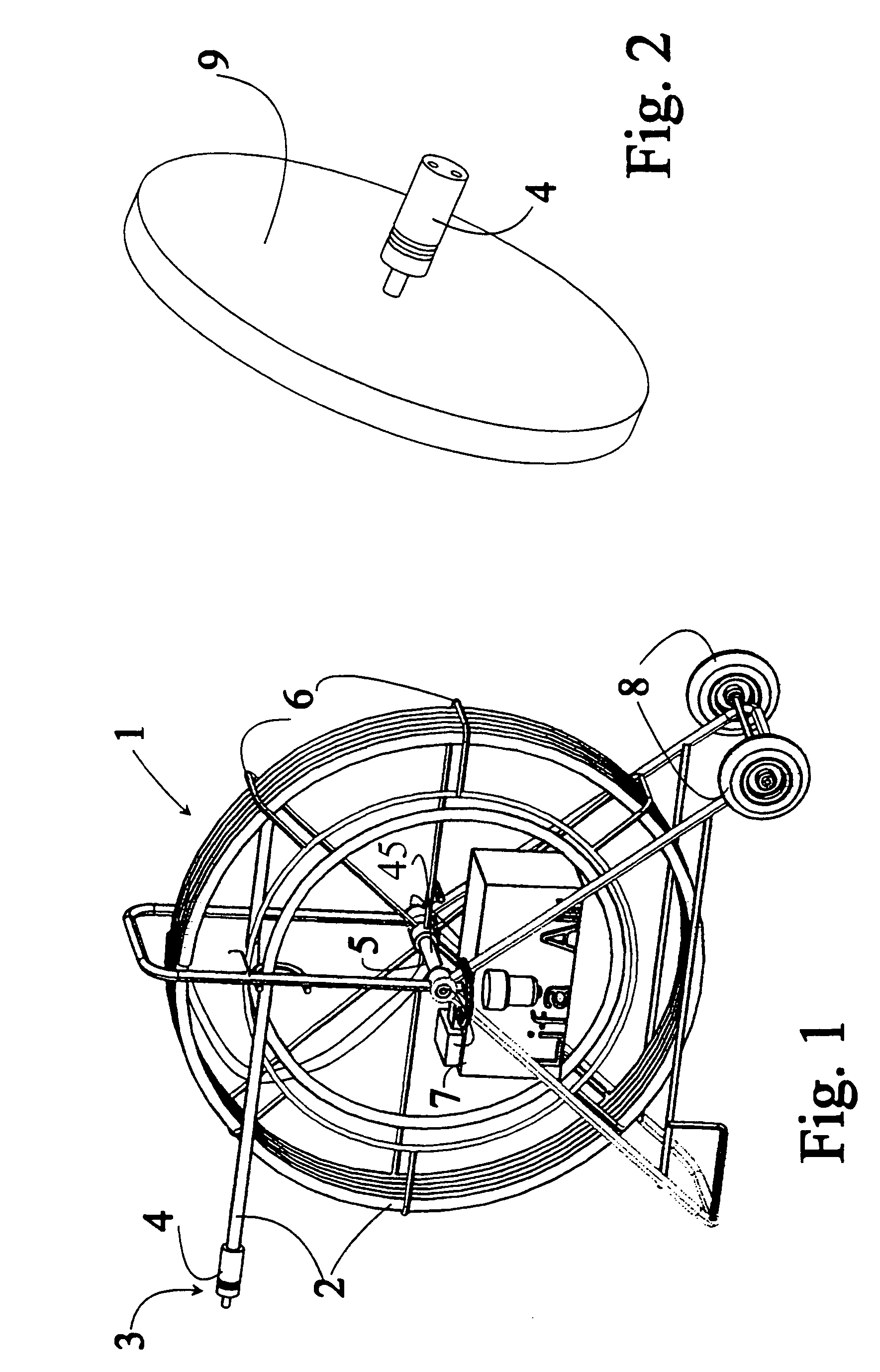
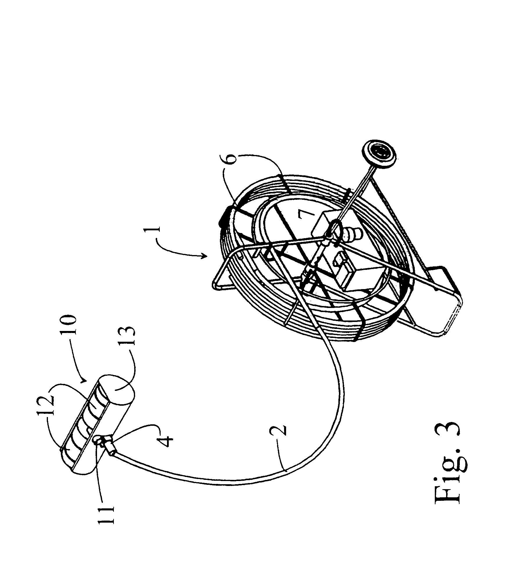
[0032]In the description the invention below, the following terminology with corresponding reference numberals will be used:[0033]1 cleaning arrangement[0034]2 guide wire cable[0035]3 cleaning end[0036]4 hydraulic motor[0037]5 feed end[0038]6 coil carriage[0039]7 hydraulic aggregate[0040]8 wheels[0041]9 radial brush[0042]10 transverse workhead[0043]11 suction connector[0044]12 cylinder brush[0045]13 hood[0046]14 herringbone gear[0047]15 suction pipe[0048]16 receiver unit[0049]17 receiver bag[0050]18 inner casing[0051]19 outer casing[0052]20 flow distributor cover[0053]21 inlet connector[0054]22 underpressure connector[0055]23 suction pipe[0056]24 underpressure unit[0057]25 exhaust outlet[0058]26 primary shaft[0059]27 secondary shaft[0060]28 gear body[0061]29 electric motor[0062]30 hydraulic pump[0063]31 1st adjustable pressure limit valve[0064]32 2nd adjustable pressure limit valve[0065]33 hydraulic filter[0066]34 1st reverse flow valve[0067]35 2nd reverse flow valve[0068]36 3rd rev...


PUM


Abstract

The present invention concerns an arrangement for cleaning ducts and chimneys, such as air conditioning ducts. The arrangement comprises a guide wire cable having a cleaning end and a feed end, a brush or some other tool being connected to the cleaning end of the guide wire cable, and a drive unit connected to the feed end of the guide wire cable, the arrangement further comprising transmission means for moving the brush by means of the drive unit. According to the invention the drive unit comprises a hydraulic pump, the transmission means are provided by hydraulic pipes arranged inside the guide wire cable, and the primary drive unit for the brush being a hydraulic motor connected to the cleaning end of the guide wire cable.

Description

CROSS REFERENCE TO RELATED APPLICATION[0001]This is a national stage application filed under 35 USC 371 based on International Application No. PCT / FI2000 / 001005 filed Nov. 16, 2000, and claims priority under 35 USC 119 of Finnish Patent Application No. 19992494 filed Nov. 23, 1999.BACKGROUND OF THE INVENTION[0002]The invention related to an arrangement for cleaning ducts and passages, such as air-conditioning ducts or chimneys.[0003]The invention also relates to a receiver unit and a transverse workhead which are part of the arrangement.[0004]According to the prior art, cleaning apparatuses and methods are used where a brush at the end of a long guide wire cable is inserted into the duct to be cleaned. The brush is moved inside the duct and for enhanced cleaning effect it is rotated or caused to make jerking movements. An alternative solution involves a technique based on intense compressed-air blasting where the cleaning end progresses inside the duct by means of compressed air. Ev...

Claims


Application Information

Patent Timeline
Patent Type & Authority Patents(United States)
IPC IPC(8): B08B9/04B08B9/047B08B9/00B08B1/00B08B5/04B08B15/04F23J3/02F24F13/02
CPCB08B5/04B08B9/047F23J3/026B08B15/04F24F2221/22
Inventor MAKIPAA, VESASALOMAKI, KAUKOVIINIKAINEN, MARKKU
Owner LIFA IAQ
Why Eureka
Try Eureka