
Reverse circulation clean out system for low pressure gas wells

a technology of gas wells and reverse circulation, which is applied in the direction of wellbore/well accessories, drilling pipes, drilling rods, etc., can solve the problems of accumulating materials into the production, affecting the recovery of oil and gas from low or under pressure reservoirs, and affecting the production efficiency of the well, so as to achieve the effect of optimum production and less damage to the formation

Active Publication Date: 2006-08-15
PRESSSOL
View PDF89 Cites 28 Cited by
  • Summary
  • Abstract
  • Description
  • Claims
  • Application Information

AI Technical Summary

Benefits of technology

[0010]The present invention allows for the clean out of well bores in a safe manner, and with less damage to the formation. This is particularly important because clean out operations generally have to be repeated several times over a period of several weeks to ensure optimum production. The invention works particularly well in low and under pressure hydrocarbon formations where existing clean out technologies can easily damage the formation.

Problems solved by technology

However, recovery of oil and gas from these low or under pressure reservoirs is difficult due to drilling damage, well stimulation damage and well completion damage.
Such damage can make the difference between a commercial well or an abandoned well.
Unfortunately, the lifting pressures used will often exceed the formation pressure thereby forcing the accumulated materials into the production zones.
Open hole completions can pose problems when performing conventional clean out operations because well bore material such as shale can collapse the well bore, cave it in, or fill up the well bore past the productive zones.
If water contacts these clays during conventional clean out operations, these clays can swell and permanently damage the producing formations.
Conventional clean out operations can also cause considerable damage to coal bed methane wells, which most often are completed open hole and are usually very low pressure.
This greatly reduces the ability of the methane gas to flow freely from the fractures in the coal and into the open hole well bore.

Method used


Image

  • Reverse circulation clean out system for low pressure gas wells
  • Reverse circulation clean out system for low pressure gas wells
  • Reverse circulation clean out system for low pressure gas wells

Examples


Embodiment Construction

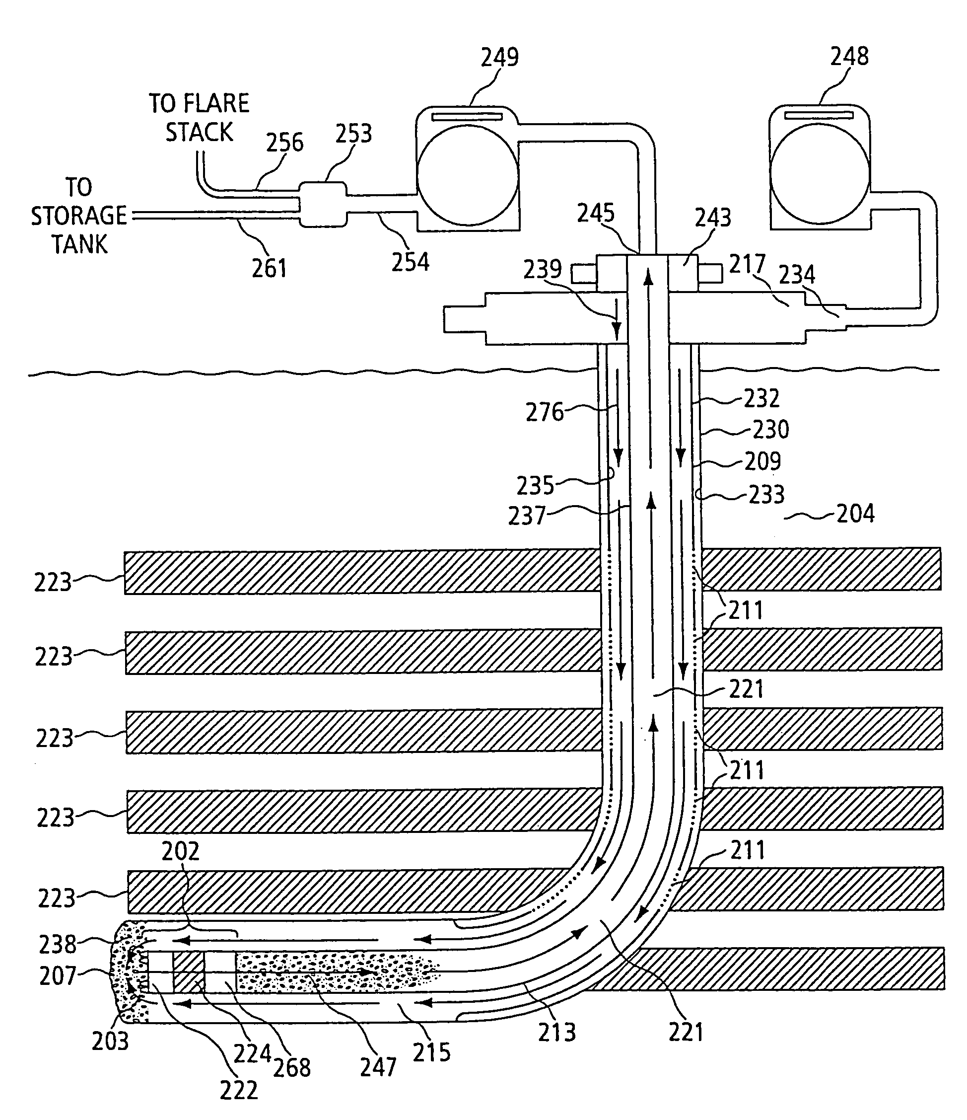
[0090]Apparatus and methods of operation of that apparatus are disclosed herein in the preferred embodiments of the invention that allow for clean out of both cased and open hole well bores in hydrocarbon formations. From these preferred embodiments, a person skilled in the art can understand how this reverse circulation clean out process can be used safely in the oil and gas industry. The clean out process of the present invention using drill pipe can use either a service rig or a drilling rig for operation.

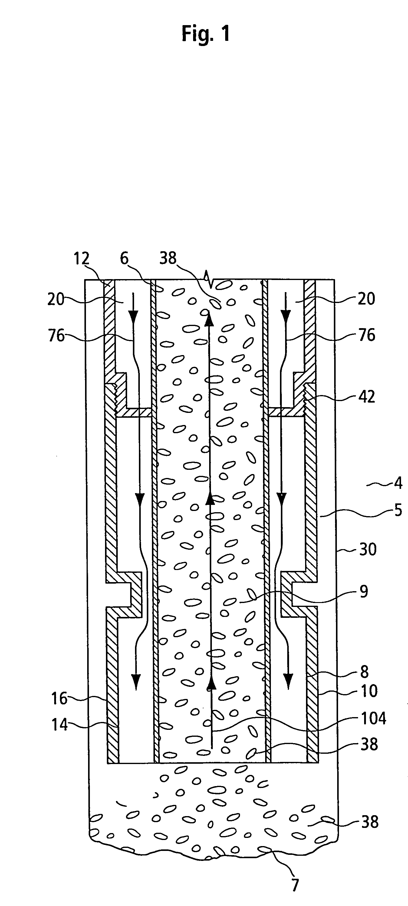
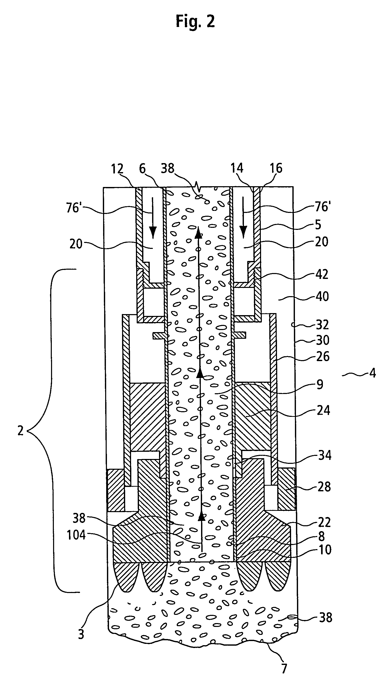
[0091]FIG. 1 is a vertical cross-section of a bottom portion of a clean out apparatus 4 of one preferred embodiment of the present invention which has been delivered into a well bore 30. At or near the bottom 7 of said well bore 30 is situated clean out material 38 comprising sand, shale, drill cuttings, drilling fluid and the like, which when removed increases the productivity of well bore 30.

[0092]Clean out apparatus 4 comprising concentric drill string 5. Concentric drill str...


PUM


Abstract

The present invention provides an apparatus and a method for removing undesirable material from a well bore in a hydrocarbon formation with minimum damage to the formation. The apparatus comprises a concentric tubing string, said concentric tubing string further comprising an inner tube means having an inner annulus therethrough and an outer tube means forming an outer annulus between said outer tube means and said inner tube means, means for introducing into said well bore a pressurized clean out medium through one of the said inner annulus and outer annulus, and means for removing said material and clean out medium through the other of the said inner annulus and said outer annulus to the surface of said well bore. In a preferred embodiment, the introducing means comprises a discharge compressor or mud pump and the removing means comprises a suctioning compressor.

Description

[0001]This application claims the benefit of U.S. Provisional Application No. 60 / 396,717, filed on Jul. 19, 2002.FIELD OF THE INVENTION[0002]The present invention relates generally to an apparatus for insertion in a well bore and a method associated therewith for removal of undesirable material. More particularly, the present invention relates to a clean out system utilizing at least two compressors together with concentric drill pipe, concentric coiled tubing, or single wall tubing inserted into the well casing.BACKGROUND OF THE INVENTION[0003]In hydrocarbon producing wells, it is desirable to remove accumulated solid particles, sediment, and / or injection fluids, such as fracturing acids, sands and drilling fluids from the well bore to avoid restriction of the flow of hydrocarbons caused by such materials. When removing such materials it is important to keep formation damage to a minimum to ensure maximum production. This is particularly important when attempting to clean out low a...

Claims


Application Information

Patent Timeline
IPC IPC(8): E21B21/00E21B21/08E21B21/10E21B21/12
CPCE21B21/08E21B21/12E21B21/10E21B2021/006E21B21/085
Inventor LIVINGSTONE, JAMES I.
Owner PRESSSOL
Learn More