Method and apparatus for micro-machined sensors using enhanced modulated integrative differential optical sensing

a technology of integrated differential optical sensing and micro-machined sensors, applied in the direction of acceleration measurement using interia forces, acceleration measurement in multiple dimensions, instruments, etc., can solve the problems of limiting the minimum detectable displacement, increasing the complexity of the mems device, and increasing the size of the micro-electronics

Inactive Publication Date: 2006-08-15
TECHNION RES & DEV FOUND LTD +1
View PDF6 Cites 26 Cited by
  • Summary
  • Abstract
  • Description
  • Claims
  • Application Information

AI Technical Summary

Benefits of technology

[0036]In accordance with a preferred method of the present invention, there is provided a method for an enhanced version of the MIDOS concept, referred to as E-MIDOS. By using this method the NE

Problems solved by technology

For several decades microelectronics progressed in decreasing size while simultaneously increasing complexity.
MEMS devices have become more complex, and have incorporated an increasing number of features, progressing from components to electronic systems.
The main factor that limits the minimum detectable displacement is the noise sources that sensing systems are susceptible to.
Spurious noise sources include mechanical noise, electrical noise, light noise, etc.
Few methods have shown the capability for sensing motions in the sub-picometer range.
Nevertheless, the tunneling effect suffers from inherent “1/f” noise, up to the range of a few Kilohertz (KHz), and its apparatus is quite difficult to realize.
Moreover, due to the close proximity required between the tip and the facing electrode, of the order of a few _ (Angstrom units), the sensing is adversely affected by a relatively

Method used


Image

  • Method and apparatus for micro-machined sensors using enhanced modulated integrative differential optical sensing
  • Method and apparatus for micro-machined sensors using enhanced modulated integrative differential optical sensing
  • Method and apparatus for micro-machined sensors using enhanced modulated integrative differential optical sensing

Examples


case study

Design Case Study

[0147]In the following, a design case study of an accelerometer employing EMIDOS is discussed. The TNEA and natural frequencies are derived for the structure, and the design considerations of the accelerometer are discussed.

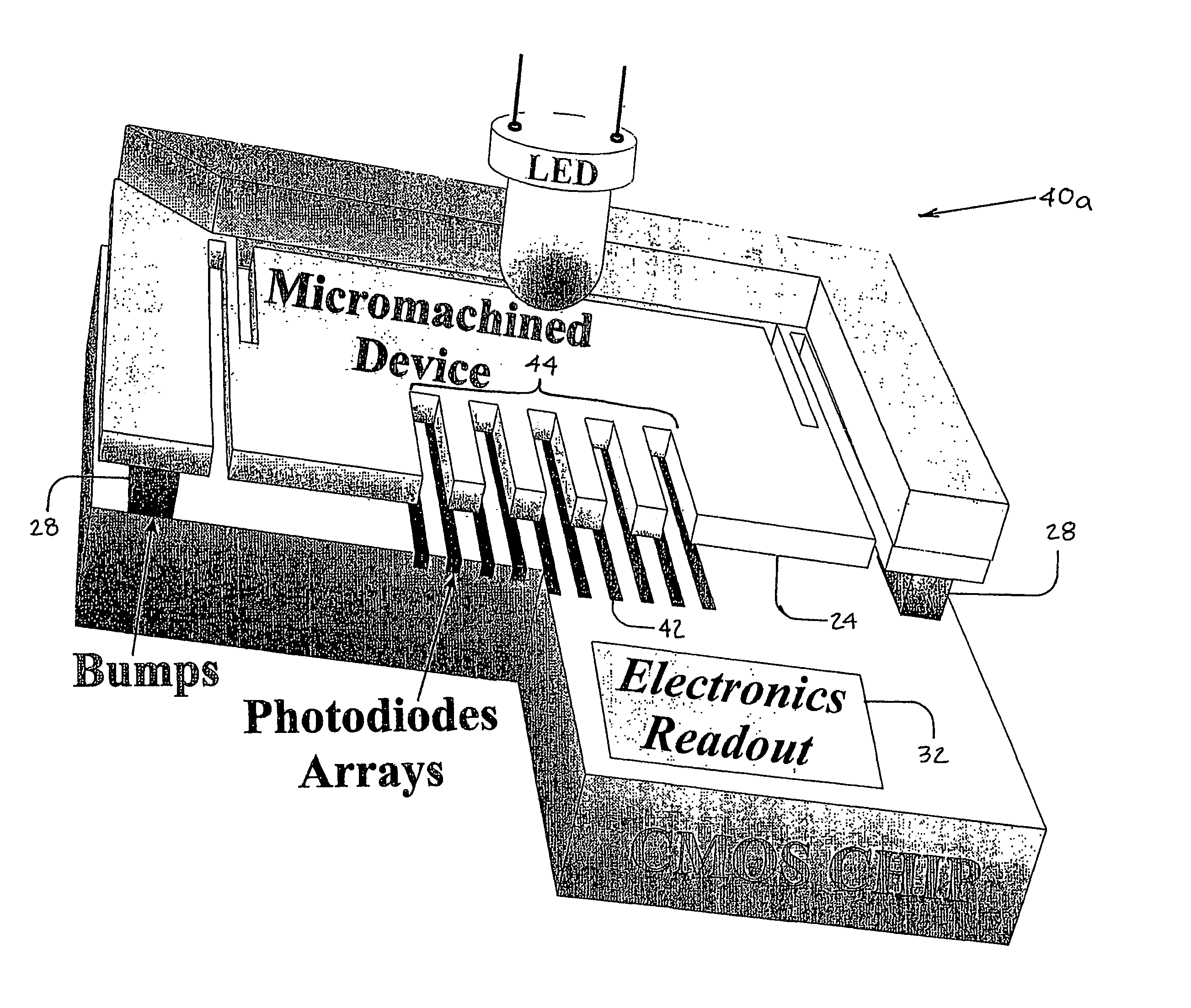
[0148]FIG. 7 is a schematic illustration of an accelerometer employing E-MIDOS 110, in accordance with an exemplary embodiment of the present invention. The suspending beams and the grid are assumed with rectangular cross-section, see the Fabrication Process, described hereinbelow. The total thickness of all the accelerometer mechanical structural elements, i.e. beams, proof-mass 24 and grid 44, is denoted by T. Grid 44 is centered with respect to proof-mass 24. It is noted that grid 44 does not fill entire proof-mass 24 and mass 24 is extended to fill most of the inner frame. This is done in order to increase the total mass and reduce the thermal-mechanical noise. Grid 44 is circumscribed by, and is not required to be extended over, the entire c...


PUM


Abstract

Method and apparatus for sensing the displacements of micromachined devices and sensors. The method is referred to as the enhanced modulated integrative differential optical sensing (EMIDOS). The target micromachined proof-mass, for which displacements are measured, includes a grid of slits. The micromachined device is bonded to a CMOS chip containing a matching photodiodes array and their readout electronics. The grid is aligned with the photociiodes. An illumination source, such as an LED, is then mounted above the micromachined device. A model for the noise equivalent displacement (NED), including mechanical, electrical and optical domains, as well as all noise sources is derived. The model predicts that displacements below 10−3 [√{square root over ( )}Hz] can be measured. The design comprises innovative inertial sensors, an accelerometer and a rategyroscope employing the EMIDOS. Performance models for the noise equivalent acceleration (NEA) and noise equivalent rate (NER) are also derived. The models show that an accelerometer with a very low NEA can be realized.

Description

CROSS-REFERENCE TO RELATED APPLICATION[0001]The present application is related to Israel Patent Application No. 122,947, filed Jan. 15, 1998, entitled “Micro-electro-opto-mechanical inertial sensor with integrative optical sensor” which is assigned to the co-assignees of the present patent application and is incorporated herein by reference.[0002]The present application claims priority of Israel Patent Application No. 139695 filed 15 Nov. 2000, assigned to the co-assignees, and entitled “METHOD AND APPARATUS FOR MICRO-MACHINED SENSORS USING ENHANCED MODULATED INTEGRATIVE DIFFERENTIAL OPTICAL SENSING”.FIELD OF THE INVENTION[0003]The present invention relates generally to sensing the motion of micro-machined devices, and specifically to sensing sub-picometer range motion in inertial grade gyroscopes and accelerometers.BACKGROUND OF THE INVENTION[0004]For several decades microelectronics progressed in decreasing size while simultaneously increasing complexity. Mechanical structures can...

Claims


Application Information

Patent Timeline
IPC IPC(8): G01R31/308B81B3/00G01P15/093G01P15/18
CPCG01P15/093G01P15/18G01P2015/0814
Inventor NEMIROVSKY, YAELDEGANI, OFIRSOCHER, ERANSETER, DAN
Owner TECHNION RES & DEV FOUND LTD
Why Eureka
Try Eureka