Power amplification by using different fixed power supply signals for the amplifier

a fixed power supply and amplifier technology, applied in the field of power amplification, can solve the problems of increasing operating costs, high dc power, increasing costs for amplifier cooling equipment, etc., and achieve the effects of reducing operational costs, enhancing power amplification, and reducing energy consumption

Inactive Publication Date: 2006-08-15
LUCENT TECH INC +1
View PDF17 Cites 40 Cited by
  • Summary
  • Abstract
  • Description
  • Claims
  • Application Information

AI Technical Summary

Benefits of technology

[0031]Consequently, some of the main merits of the inventive efficiency enhanced power amplification approach are the reduced operational costs including lower energy consumption, the lower efforts for thermal management, for the amplifier itself and the component the amplifier is embedded within as well as the possibility to design more environmental friendly amplifiers which is in particular important for wireless systems, cellular networks, terrestrial broadcasting systems and satellite based transmission systems.

Problems solved by technology

Normally it is not possible to get an optimum for all the above-mentioned three parameters at the same time as each of these parameters is requiring at least a slightly different input / output matching network.
As a consequence, the high DC power increases operating costs and the large amount of dissipated heat increases costs for the amplifier cooling equipment including operating costs for active cooling systems, such as air conditioning, and material costs for bigger heat-sinks and better heat conducting materials.
However, one of the most drawbacks of this concept is, that two amplifiers with a special controlling and combining network are needed.
As a disadvantageous consequence, two complete amplifier chains from the baseband up to the output of the amplifier unit are necessary and the combining network at the output is difficult to realize.
However, the controlling of the supply voltage or current for the amplifier is difficult to achieve because of the speed of the necessary voltage and current changes.
Furthermore, the efficiency of the necessary DC / DC converter worsens the efficiency budget of the whole amplifier unit.
Thus the drawbacks of the known EER technique are lying mainly in the fact, that even the most recent DC / DC converters are not able to provide the fast changes in the amplifier supply voltage and / or current needed to reconstruct the amplitude of the original signal at the amplifier unit output, which holds true especially for broadband signals like a UMTS (Universal Mobile Telecommunication System) signal with high power amplifiers.

Method used


Image

  • Power amplification by using different fixed power supply signals for the amplifier
  • Power amplification by using different fixed power supply signals for the amplifier
  • Power amplification by using different fixed power supply signals for the amplifier

Examples


Embodiment Construction

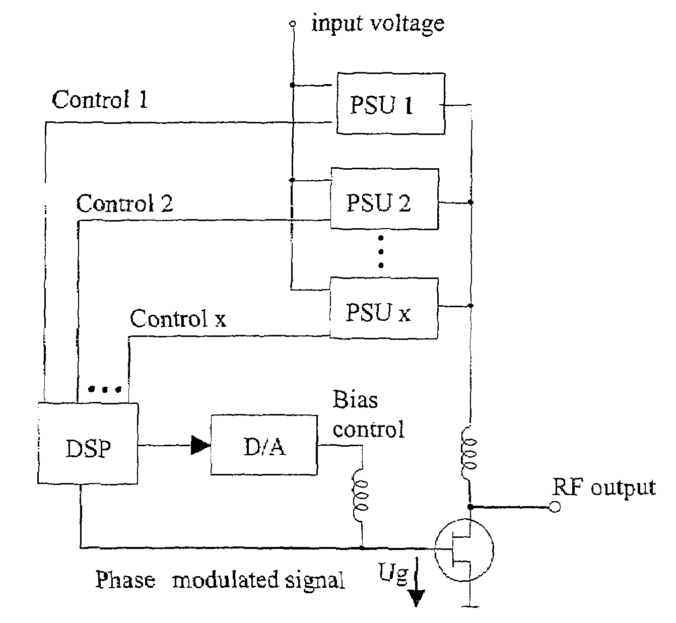
[0038]With regard to the following exemplar description and to form a basis for an easier understanding of the inventive approach, reference is made in particular to the afore-discussed known efficiency enhancement concept EER (Envelope Elimination and Restoration), according to which the amplifier input signal is converted to a purely phase modulated signal and the amplitude modulated part of the input signal is processed separately.

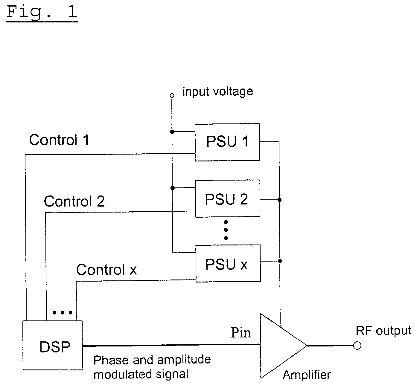
[0039]Regarding the advantageous but exemplar inventive embodiments, such a conversion process may be done with help of a limiter or, as depicted in FIG. 1 and FIG. 3, with the help of modern signal processing at the baseband frequency using a digital signal processor DSP to which the baseband is fed (not depicted in FIG. 1 and FIG. 3).

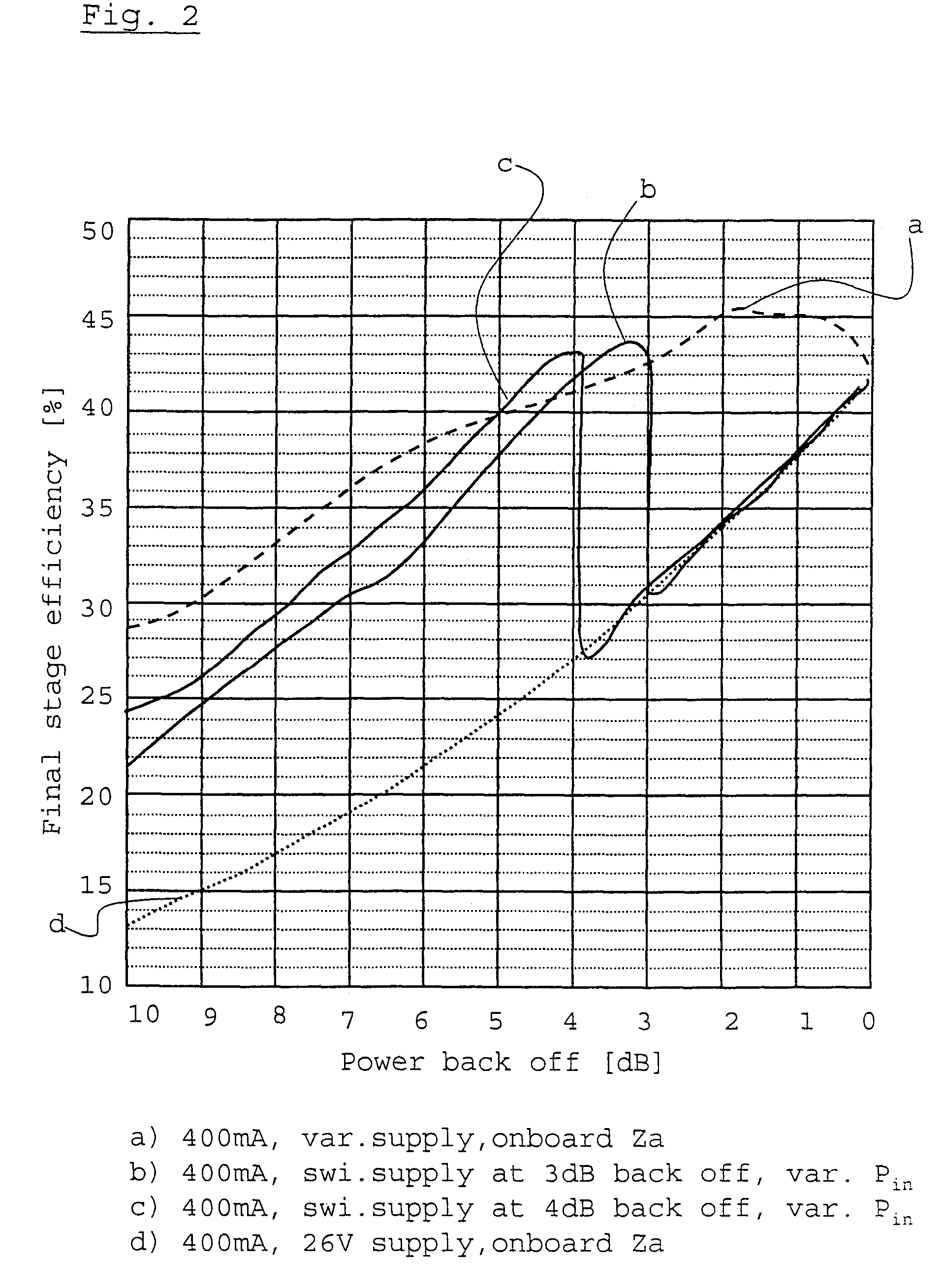
[0040]Then conventionally, at the last stage of the amplifier chain the amplitude part of the original input signal should be reconstructed by changing the supply voltage of the final stage amplifier. Hence, to be able to...


PUM


Abstract

The present invention proposes a power amplification under variable envelope excitation, wherein an original input signal at least is converted into a phase modulated signal part, at least the phase modulated signal part is fed to an input port of an amplifier unit, the input signal is amplified by dynamically selecting a fixed power supply (PSU 1, PSU 2, PSU 3) for the amplifier unit, and wherein the amplitude content of the original input signal is reconstructed by changing dependent on the respective provided power supply a further controllable input of the amplifier unit, in particular the input power level (Pin) and/or the biasing voltage (Ug) and/or biasing current at the control input of the amplifier unit, during said step of amplifying.

Description

CROSS REFERENCE TO RELATED APPLICATION[0001]This application claims priority of European Patent Application No. 02254808.5 filed on Jul. 9, 2002.TECHNICAL FIELD[0002]The present invention relates to power amplification.BACKGROUND OF THE INVENTION[0003]Conventionally, power amplifier concepts operate the power amplifiers with fixed input and output loads. These loads are usually chosen such that the gain, the output power or the efficiency is optimized depending on the need of the specific application. In particular regarding mobile communication systems, such an application may be a battery-powered amplifier in a user equipment or mobile station or may be an amplifier for a base station.[0004]In case of battery powered amplifier the load usually is chosen such that the efficiency is optimized, wherein in case of an amplifier for a base station the optimization for a maximum output power is needed.[0005]Normally it is not possible to get an optimum for all the above-mentioned three p...

Claims


Application Information

Patent Timeline
Patent Type & Authority Patents(United States)
IPC IPC(8): H03F3/38H04B1/04H03F1/02
CPCH03F1/0227H03F1/0261H03F1/025H03F2200/511
Inventor FRIEDEL, BERNDRITTER, KAI-UWE
Owner LUCENT TECH INC
Why Eureka
Try Eureka