

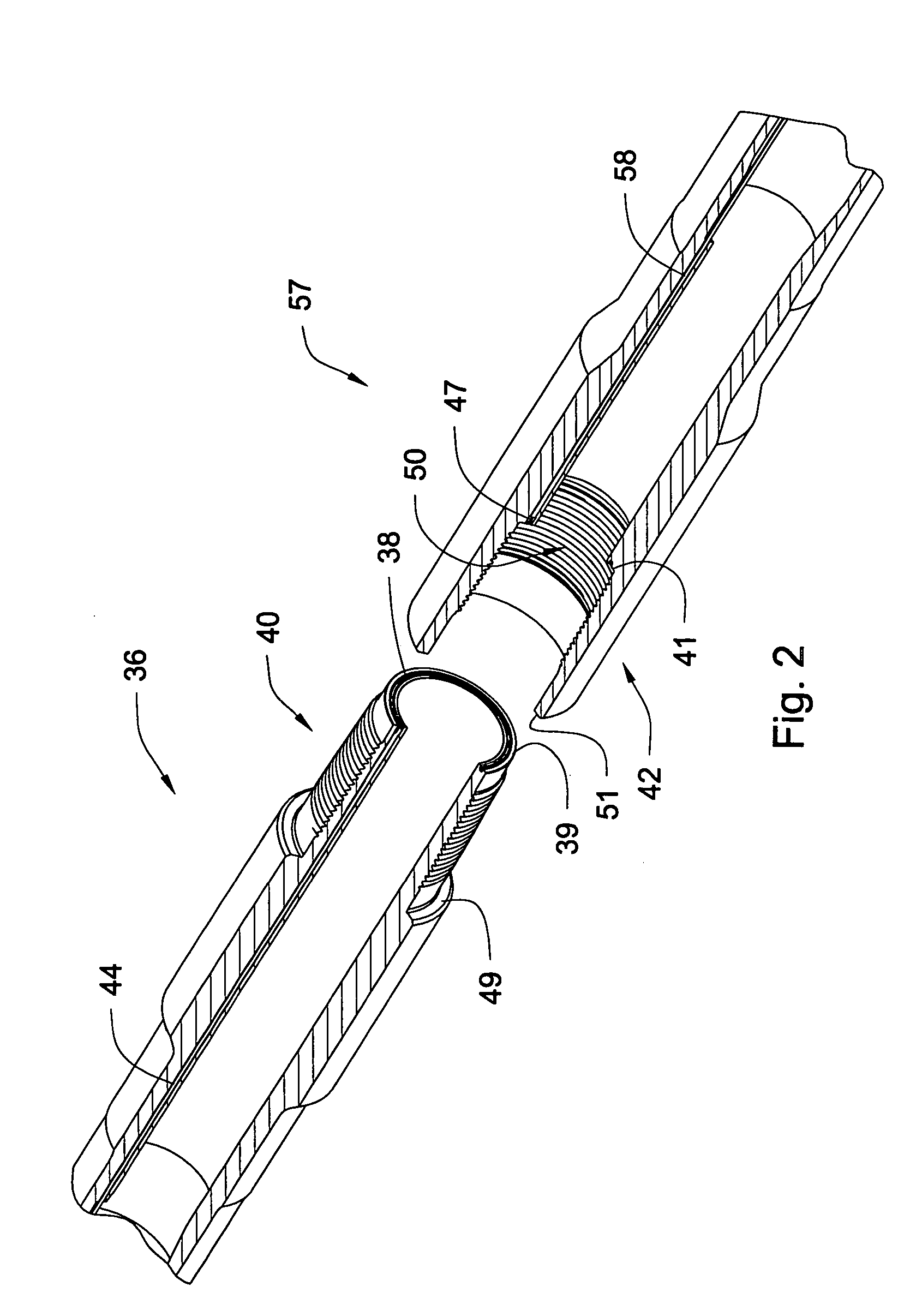
Element of an inductive coupler
a technology of inductive couplers and elements, applied in the direction of transformers/inductances, magnetic cores, continuously variable inductances/transformers, etc., can solve the problems of inductive couplers, material, such as ferrite, may crack, and the pressure felt by elements may crack along scored lines
- Summary
- Abstract
- Description
- Claims
- Application Information
AI Technical Summary
Benefits of technology
Problems solved by technology
Method used
Image

Examples
Embodiment Construction
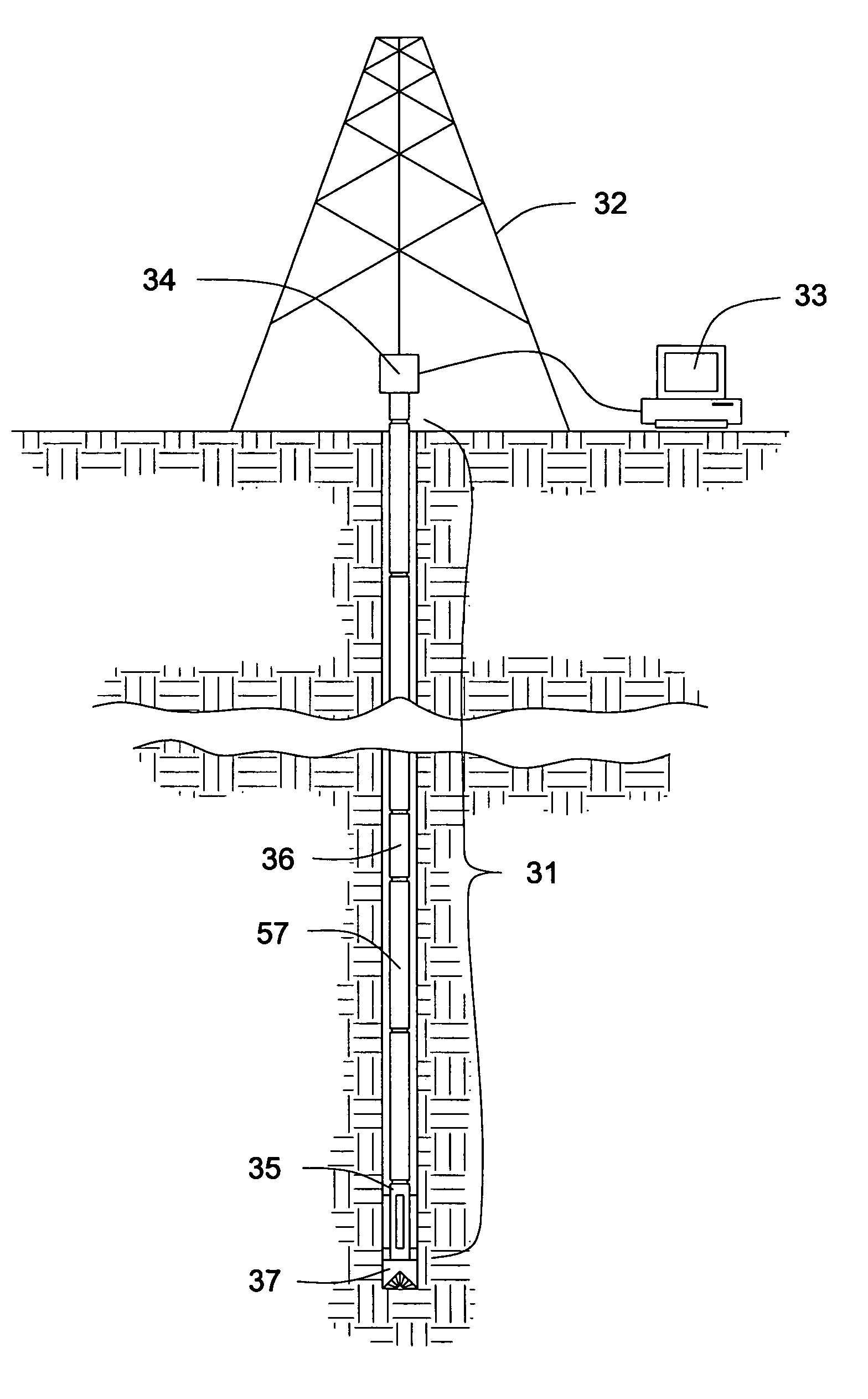
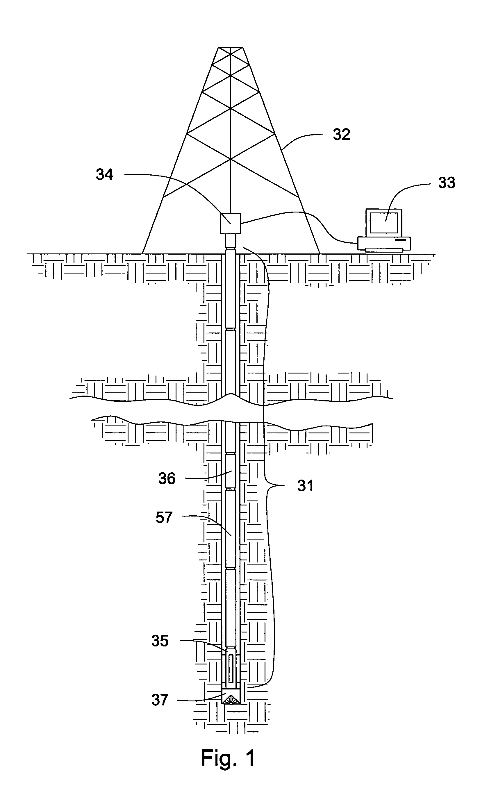
[0017]FIG. 1 shows an embodiment of a downhole tool string 31 suspended in a well bore by a derrick 32. Surface equipment 33, such as a computer, connects to a data swivel 34. The data swivel 34 is adapted to transmit data to and from an integrated transmission network while the downhole tool string 31 is rotating. The integrated transmission network comprises the transmission systems of the individual components 35, 36, 57 of the downhole tool string 31. Preferably the downhole component is a pipe 36, 57. Alternatively the downhole component is a tool 35. Tools 35 may be located in the bottom hole assembly 37 or along the length of the downhole tool string 31. The tools 35 on a bottom hole assembly 37 may be sensors, drill bits, motors, hammers, and steering elements. The tools 35 located along the downhole tool string 31 may be links, jars, seismic sources, seismic receivers, sensors, and other tools that aid in the operations of the downhole tool string 31. Different sensors are ...
PUM
| Property | Measurement | Unit |
|---|---|---|
| magnetically conductive | aaaaa | aaaaa |
| pressure | aaaaa | aaaaa |
| electrically insulating | aaaaa | aaaaa |
Abstract
Description
Claims
Application Information