

Phase to amplitude H-Bridge switching circuit
- Summary
- Abstract
- Description
- Claims
- Application Information
AI Technical Summary
Benefits of technology
Problems solved by technology
Method used
Image

Examples
Embodiment Construction
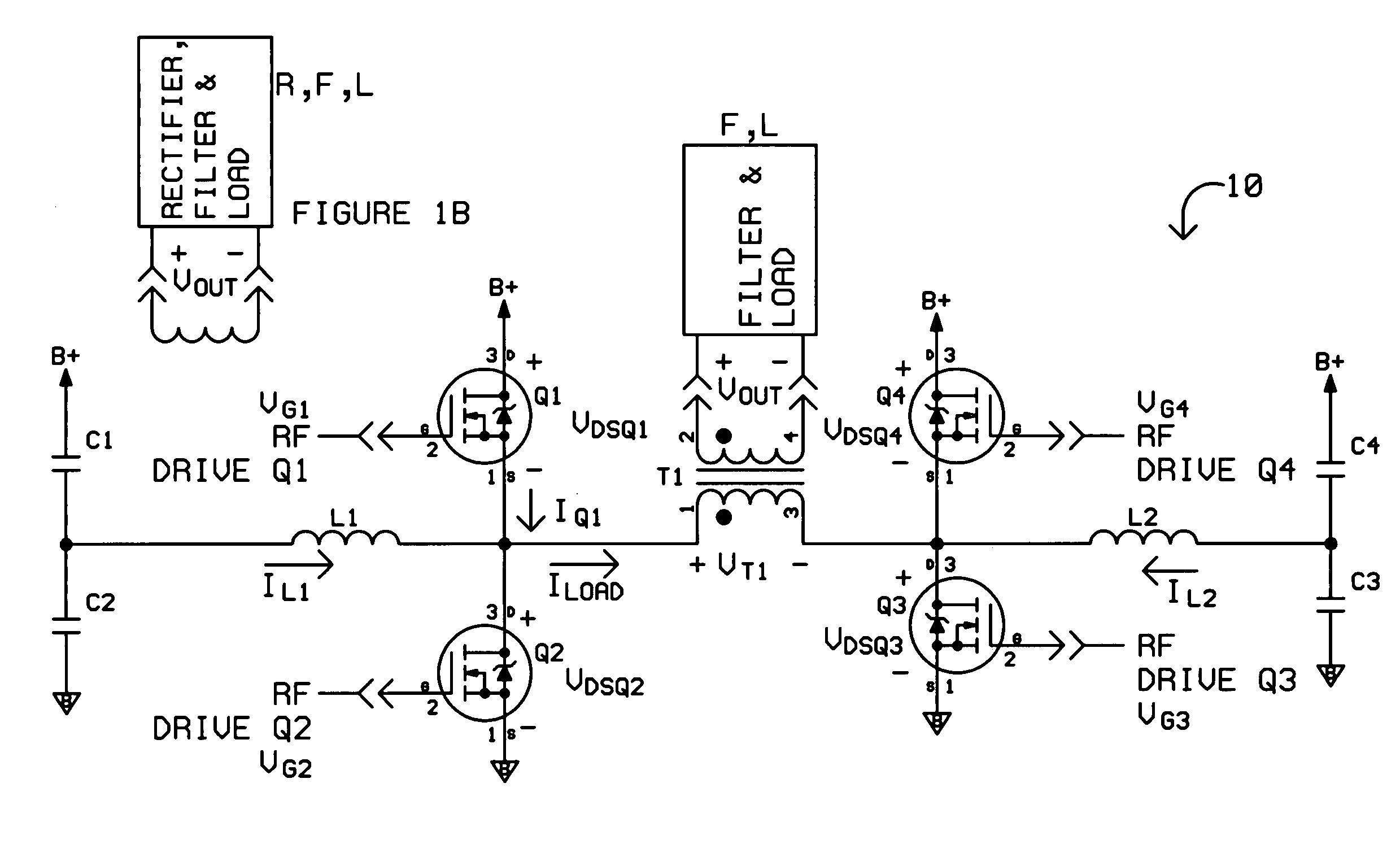
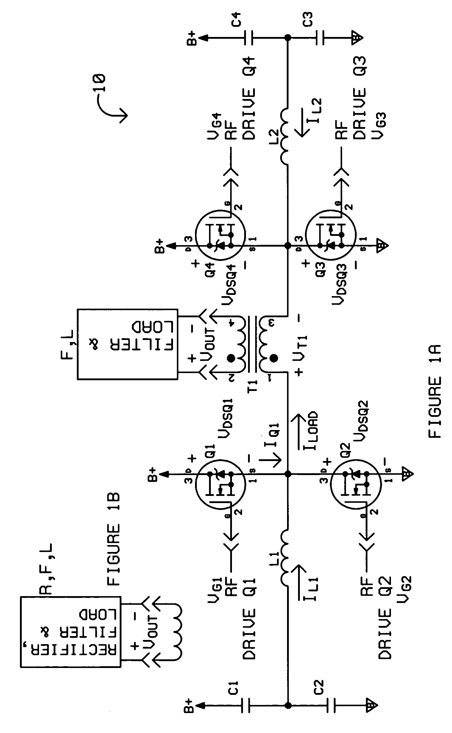
[0027]Various embodiments of the invention are described in the following text. FIGS. 1A, 1B illustrate a schematic diagram of an embodiment of the inventive power amplifier H-Bridge circuit 10. FIG. 1A shows the circuit used to feed a filter and load F, L for power amplification, and FIG. 1B shows the replacement of the filter and load F, L with a rectifier, filter, and load R, F, L for use as a power supply.
[0028]FIGS. 8 and 9 illustrate an exemplary context in which the H-Bridge circuit 10 may be used for an AM-band PA, and thus provide an overview of an applied variation of an inventive embodiment.
[0029]As illustrated in FIG. 8, an RF system 100 comprises an audio source 102, an RF signal generator 104, and a Global Positioning System (GPS) 106. A power amplifier power supply 110 and low voltage power supply 118 are used to supply power to the various components of the RF system 100 (numbers in parentheses in FIG. 8 indicate the number of individual components that may be used i...
PUM
 Abstract
Description
Claims
Application Information