Motor drive apparatus having input power supply voltage adjustment function

a technology of motor drive and function, which is applied in the direction of electric variable regulation, process and machine control, instruments, etc., can solve the problems of shortened life of motor drive apparatus and a variety of peripheral devices, degrading motor control accuracy, etc., and achieves increased output of motor, increased heat generated by inverter, and increased switching loss.

Active Publication Date: 2020-02-13
FANUC LTD
View PDF3 Cites 4 Cited by
  • Summary
  • Abstract
  • Description
  • Claims
  • Application Information

AI Technical Summary

Benefits of technology

[0008]Heat generated by a converter, an inverter and a motor of a motor drive apparatus causes a drop in the power factor or malfunction of the motor drive apparatus, resulting in damages and shortened lives of the motor drive apparatus and a variety of peripheral devices. For example, in the motor drive apparatus, as the voltage at a DC link (hereinafter, simply referred to as the “DC link voltage”) located between the converter and the inverter is larger, the output of the motor can be increased; on the other hand, the switching loss of the inverter is increased and heat generated from the inverter rises. In addition, for example, when the motor is driven while maintaining a certain motor output, as the DC link voltage of the motor drive apparatus is higher, the current that flows in the converter and the motor decreases, which suppresses heat generation therefrom; however, heat generated from the inverter rises and the actual resolution of a voltage command to the inverter decreases, resulting in degrading accuracy in motor control. Whereas, when the motor is driven while maintaining a certain motor output, as the DC link voltage of the motor drive apparatus is lower, heat generated from the inverter becomes lower and the actual resolution of a voltage command to the inverter is improved, enabling motor control with high accuracy; however, heat generated from the converter and the motor becomes higher. Therefore, a technique that allows efficient motor control while suppressing heat generation from each unit is desired for the motor drive apparatus.

Problems solved by technology

Heat generated by a converter, an inverter and a motor of a motor drive apparatus causes a drop in the power factor or malfunction of the motor drive apparatus, resulting in damages and shortened lives of the motor drive apparatus and a variety of peripheral devices.
In addition, for example, when the motor is driven while maintaining a certain motor output, as the DC link voltage of the motor drive apparatus is higher, the current that flows in the converter and the motor decreases, which suppresses heat generation therefrom; however, heat generated from the inverter rises and the actual resolution of a voltage command to the inverter decreases, resulting in degrading accuracy in motor control.

Method used


Image

  • Motor drive apparatus having input power supply voltage adjustment function
  • Motor drive apparatus having input power supply voltage adjustment function
  • Motor drive apparatus having input power supply voltage adjustment function

Examples


first embodiment

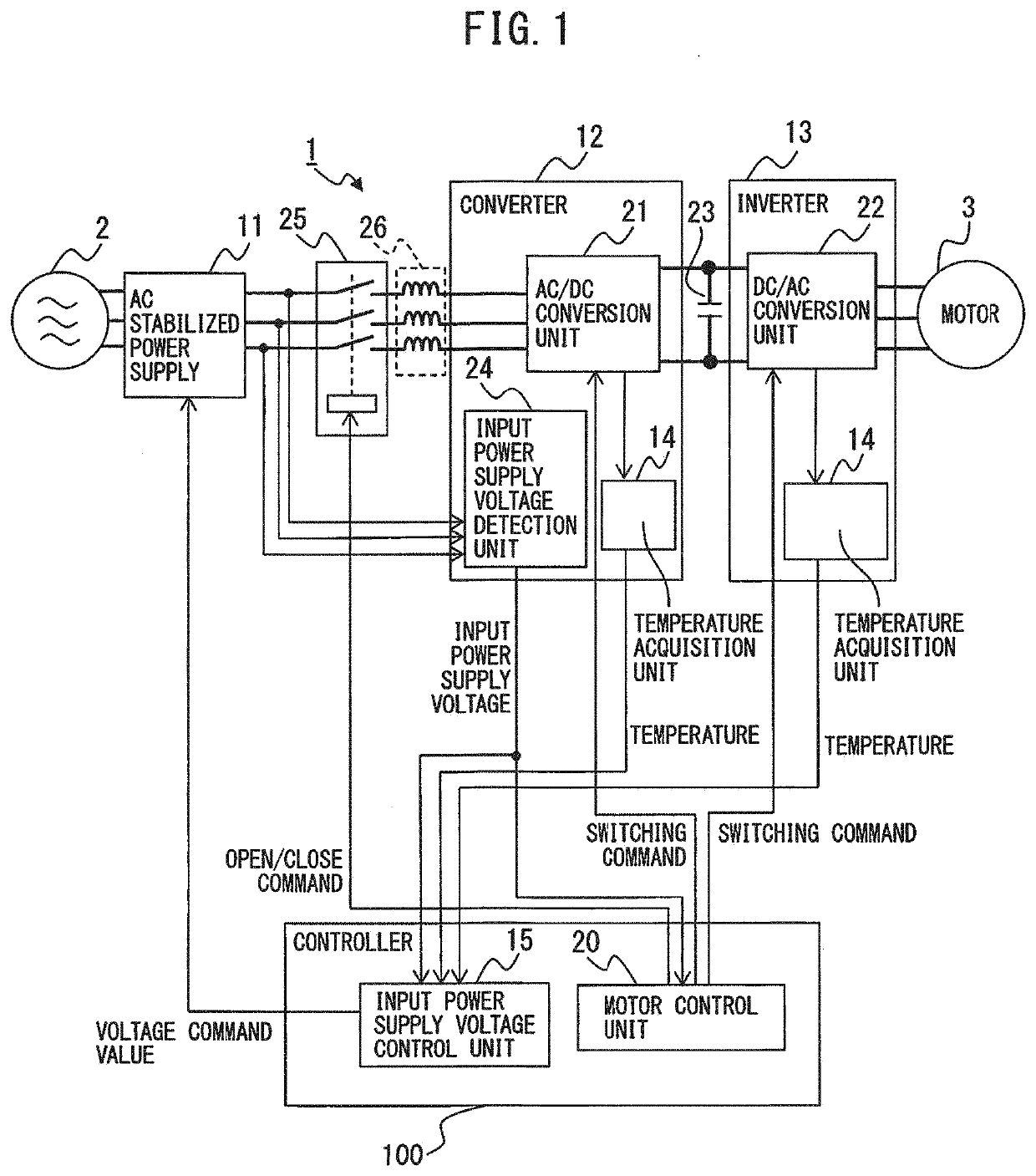
[0019]FIG. 1 is a diagram for illustrating a motor drive apparatus according to the present disclosure.

[0020]As an example, a case where a motor drive apparatus 1 that is connected to a commercial AC power source 2 controls one AC motor (hereinafter, simply referred to as the “motor”) 3 will be described. The number of the motors 3 does not particularly limit the present embodiment and may be a different number. Note that the numbers of phases of the commercial AC power source 2 and the motor 3 do not particularly limit the present embodiment, and a three-phase or single-phase configuration, for example, may be used. Examples of the commercial AC power source 2 include a three-phase AC 400 V power source, a three-phase AC 200 V power source, a three-phase AC 600 V power source, and a single-phase 100 V power source. In addition, the type of the motor 3 does not particularly limit the present embodiment and may be, for example, an induction motor, or a synchronous motor. Machines in ...


PUM


Abstract

A motor drive apparatus includes an AC stabilized power supply configured to convert AC voltage of a commercial AC power source into input power supply voltage according to a received voltage command value and output the input power supply voltage, a converter configured to convert the input power supply voltage into DC voltage and output the DC voltage to a DC link, an inverter configured to convert the DC voltage at the DC link into AC voltage for driving a motor, and an input power supply voltage control unit configured to control the input power supply voltage that is output by the AC stabilized power supply.

Description

BACKGROUND OF THE INVENTION1. Field of the Invention[0001]The present invention relates to a motor drive apparatus having an input power supply voltage adjustment function.2. Description of the Related Art[0002]A motor drive apparatus that drives a motor in a machine tool, forging machinery, an injection molding machine, industrial machinery, or a variety of robots, converts, by a converter (a rectifier), AC power that is supplied from an AC power source into DC power and outputs the DC power to a DC link, then, converts, by an inverter, the DC power in the DC link into AC power and supplies this AC power as driving power to a motor that is provided for each drive axis.[0003]In the motor drive apparatus, the inverter that supplies driving power to the motor includes a bridge circuit of power devices (semiconductor switching devices) and diodes that are connected in anti-parallel to the power devices. The inverter converts the input DC voltage (i.e., the DC voltage at the DC link) in...

Claims


Application Information

Patent Timeline
Patent Type & Authority Applications(United States)
IPC IPC(8): H02P29/60H02P27/06H02H7/08H02P1/46H02M3/158H02P29/02
CPCH02P27/06H02M2001/0067H02P29/02H02H7/0833H02P1/46H02P29/60H02M3/158G05D23/00H02M5/44H02M1/0054H02M1/327Y02B70/10H02M1/0067
Inventor KUROKI, WATARU
Owner FANUC LTD
Why Eureka
Try Eureka