Eureka AIR delivers breakthrough ideas for toughest innovation challenges, trusted by R&D personnel around the world.

Radio-communication control method and equipment

a radio communication control and equipment technology, applied in the field of wireless access system and transmission system, can solve the problems of data signal demodulation erroneously, data packet collision, and the inability to increase so as to improve the throughput of the entire system, control the deterioration of throughput, and eliminate the collision of data packets

Inactive Publication Date: 2006-08-15
HITACHI LTD
View PDF3 Cites 23 Cited by
  • Summary
  • Abstract
  • Description
  • Claims
  • Application Information

AI Technical Summary

Benefits of technology

[0009]For the purpose of improving the throughputs of user terminals in the non-interference domain, the present invention provides, in order to solve the problems described above, a wireless access system to control deterioration of the throughput due to collision of data packets in which the simultaneous communications are performed from a plurality of access points to the user terminals in the non-interference domain and the time-divided communications are performed from carrier senses to user terminals in the interference domain, utilizing a means to judge whether the user terminals associated with the access points are in the interference domain or in the non-interference domain and a means for time division of the transmission time from the access points to the user terminals in the non-interference domain and the user terminals in the interference domain.

Problems solved by technology

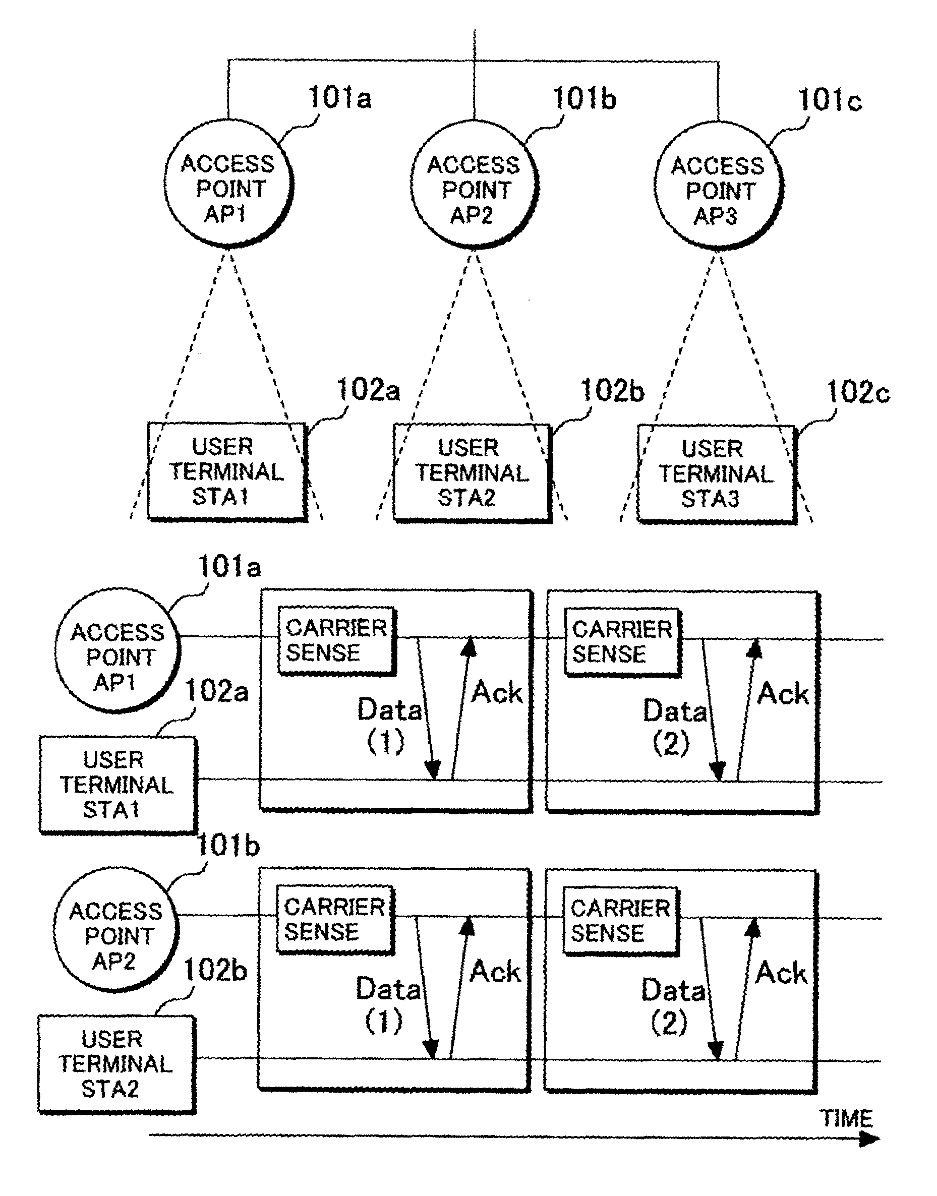
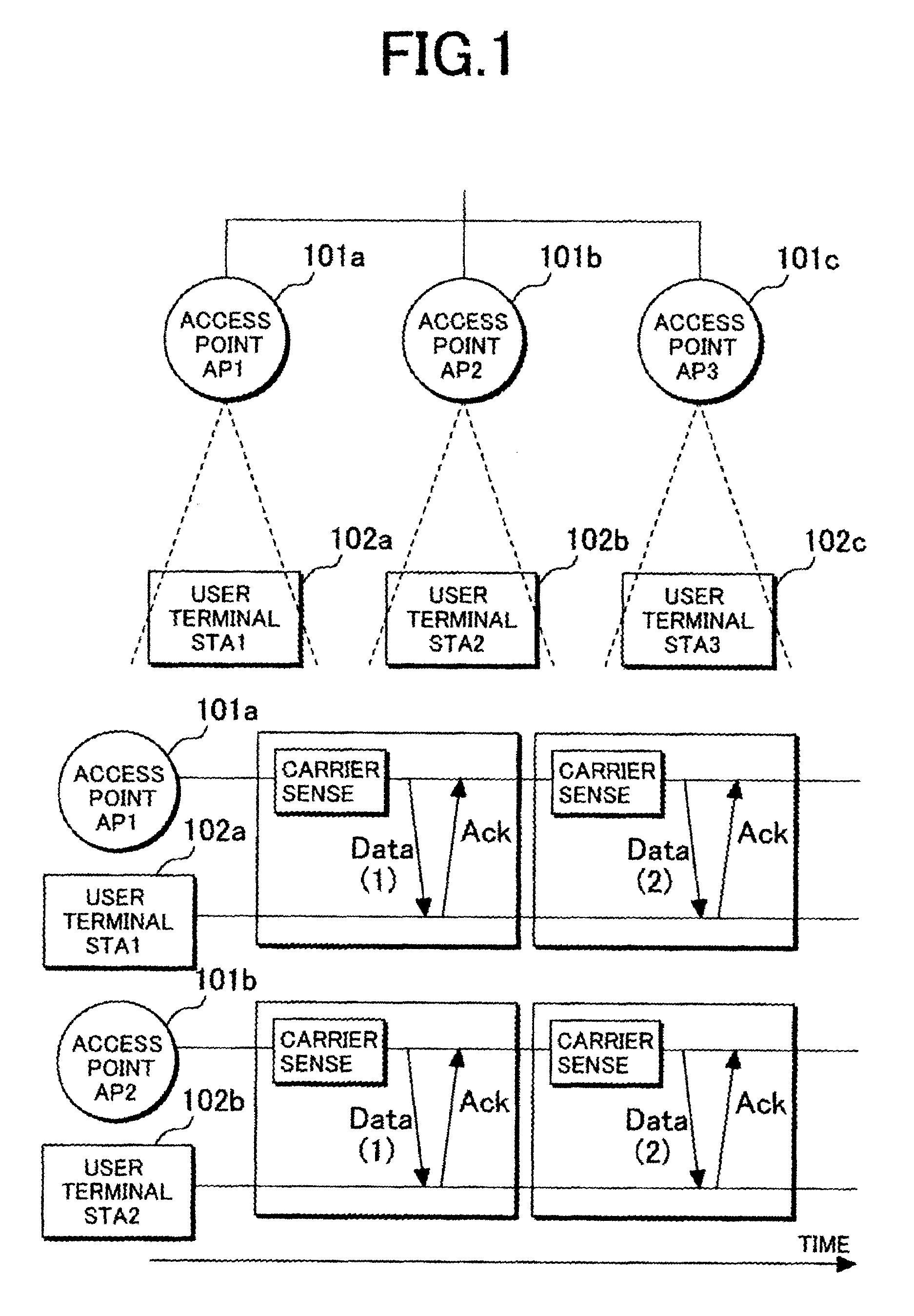
In the existing wireless LAN, interference may be avoided through time multiplexing of the communication time between a plurality of user terminals and access points with a structure of carrier sense provided to detect communication devices which are making communication using the common frequency band but here rises a problem that since amount of data which can be transmitted in the unit time does not increase, the throughput of the entire system does not increase even when the number of access points is increased and thereby the throughput of an access point is lowered.
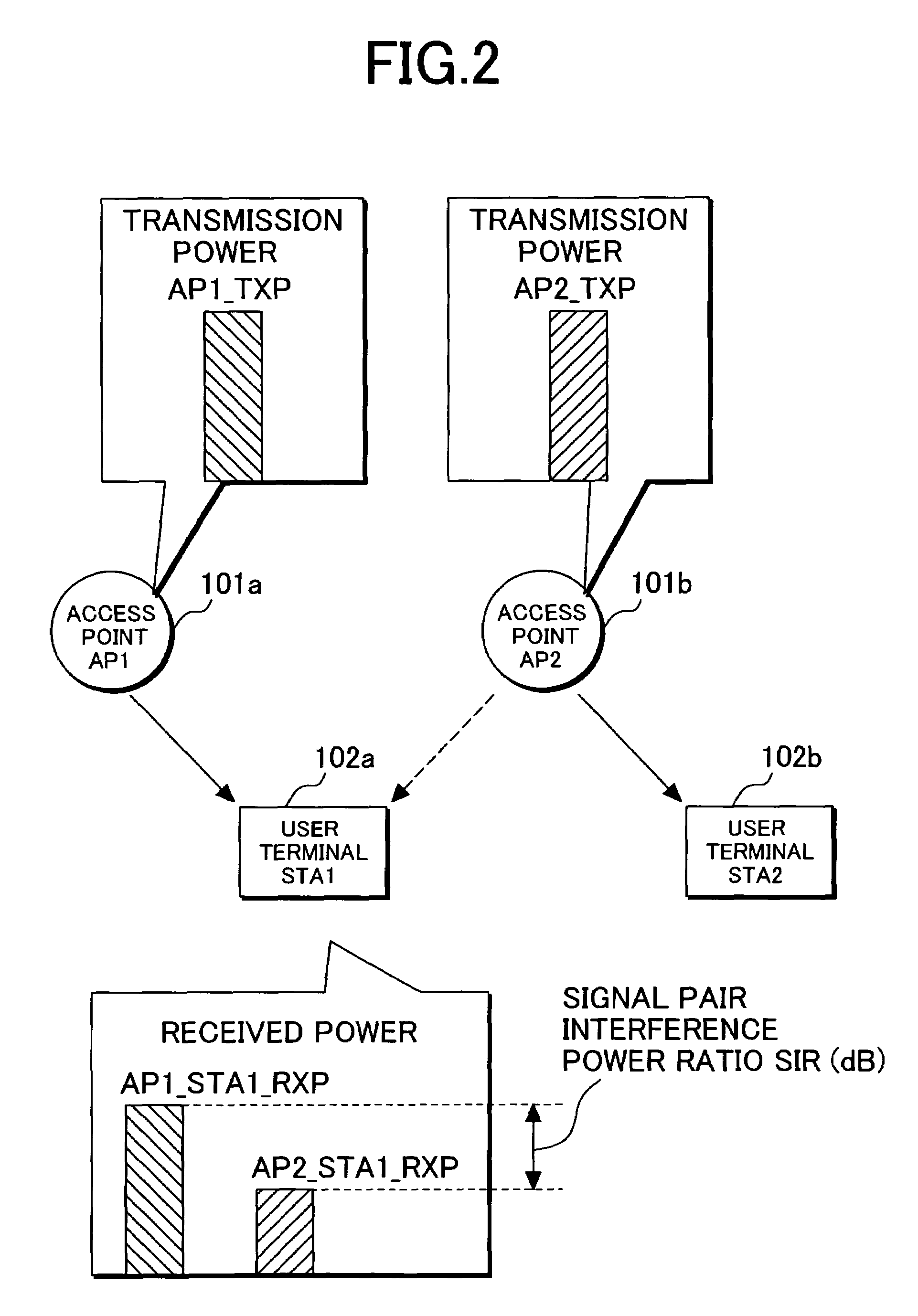
Although, depending on the demodulation performance of a receiver, when the signal pair interference power ratio SIR is equal to or higher than the desired signal pair interference power ratio SIR_req, the data signal is demodulated correctly, but if it is equal to or lower than the desired signal pair interference power ratio SIR_req, the data signal is demodulated erroneously due to the collision of packets.
When two access points described above make communications simultaneously to the user terminals in this interference domain, here rises a problem that data is lost due to the collision of packets.

Method used


Image

  • Radio-communication control method and equipment
  • Radio-communication control method and equipment
  • Radio-communication control method and equipment

Examples


Embodiment Construction

[0025]The preferred embodiment of the present invention will be described with reference to the accompanying drawings.

[0026]FIG. 4 is an explanatory diagram of a time dividing method of transmitting time for each user terminal in the preferred embodiment of the present invention. There is described an example of data transmissions to user terminals 102a and 102c from an access point 101a and to user terminals 102b and 102d from an access point 101b. Here, it is assumed that the user terminals 102a and 102b are provided in the non-interference domain, while the user terminals 102c and 102d in the interference domain. First, there is described an example of simultaneous communications to the user terminals 102a and 102b provided in the non-interference domain from the access points 101a and 101b. The time required for simultaneous communications is hereinafter referred to as transmission time for all AP to user terminals in non-interference domain T_noint. Since the predetermined sign...


PUM


Abstract

A signal pair interference power ratio of the received signal at a user terminal is obtained and this ratio is then compared with the signal pair interference power ratio required for correct demodulation. Accordingly, the user terminals can be classified into those in the non-interference domain and those in the interference domain. A plurality of access points make the simultaneous communications to the user terminals in the non-interference domain and also make the communications on the time-division basis to the user terminals in the interference domain. Thereby, it is now possible to solve the problem, in the communication system in which the total throughput of the system can be improved through simultaneous transmissions from a plurality of access points with the wireless access system to connect the user terminals to the wired network via the access points, that the throughput of the user terminal which cannot demodulate correctly the desired signal if the data packets collide with each other is more deteriorated than the user terminal which can correctly demodulate the desired signal because the desired signal pair interference power ratio is large even when the data packets collide with each other.

Description

FIELD OF THE INVENTION[0001]The present invention relates to wireless access system and transmission system in radio-communication systems.BACKGROUND OF THE INVENTION[0002]In the conventional wireless access system, user terminals are connected to a wired network as represented by the wireless LAN via access points in order to enjoy the Internet services. In the existing wireless LAN, interference may be avoided through time multiplexing of the communication time between a plurality of user terminals and access points with a structure of carrier sense provided to detect communication devices which are making communication using the common frequency band but here rises a problem that since amount of data which can be transmitted in the unit time does not increase, the throughput of the entire system does not increase even when the number of access points is increased and thereby the throughput of an access point is lowered.[0003]The JP-B No. 180775 / 2002 (U.S. patent Ser. No. 10 / 449,1...

Claims


Application Information

Patent Timeline
Patent Type & Authority Patents(United States)
IPC IPC(8): H04B7/00H04Q7/20H04B7/26H04B7/005H04B7/02H04L12/28H04W16/02H04W16/30H04W52/24H04W64/00H04W72/54H04W74/02H04W76/02H04W84/12
CPCH04W74/02H04W52/24H04B7/022H04W72/08H04W84/12H04W72/54
Inventor TAMAKI, TSUYOSHITAMAKI, SATOSHI
Owner HITACHI LTD
Why Eureka
Eureka Blog
Learn More