Graphic arts die and support plate assembly

a technology of support plate and die, which is applied in the direction of manufacturing tools, cutting tools, shaping tools, etc., can solve the problems of pressing chase, high cost of press chase, and high time consumption of foil stamping, embossing, or die cutting dies on apertured chases, flat or cylindrical,

Active Publication Date: 2006-08-29
UNIVERSAL ENGRAVING
View PDF42 Cites 26 Cited by
  • Summary
  • Abstract
  • Description
  • Claims
  • Application Information

AI Technical Summary

Benefits of technology

[0014]Thus, the engraver may furnish to its customer a completed flat graphic arts die assembly ready to be mounted on the apertured chase of a flat bed press or a multiplicity of curved die carrier plates and arcuate dies that may be mounted on the apertured cylindrical chase of a rotary press. The press operator is therefore not required as in the past to meticulously and successively mount a series of foil stamping, embossing, or die cutting dies on a flat bed chase or rotary press chase. Likewise, dedication of a flat or cylindrical chase with mounted dies thereon for high volume jobs is no longer necessary, thus freeing up chases and thereby decreasing the need for additional chases, and toggles, and significantly reducing make ready of the press for foil stamping, embossing, or die cutting jobs on flat bed as well as rotary presses.
[0016]In another embodiment of the invention, a plurality of separate curved die carrier plates are provided, each of which has an inner face adapted to complementally engage the cylindrical surface of a rotary press chase. Each of the curved carrier plates is designed to receive one or more complementally configured curved dies. The separate die carriers are each of a curvature less than 180° so that the carriers may be mounted on the rotary press chase without removal of an end plate of the press. Structure is provided for facilitating registration of all of the curved die carriers with respect to one another and with a circumferentially oriented center line of the cylindrical press platen.
[0020]Each die is also preferably provided with at least two alignment apertures therein outboard of the design defining surface of the die and that align with the respective orifices in the support member. Thus, by inserting temporary pins or the like in the apertures of each die and introducing the pins into respective orifices in the support member, each die may be maintained in its precise predetermined position on the support plate until the connector nuts are snugged down against the surface of the die plate. Additionally, the provision of the alignment apertures and orifices permit a die to be returned to its original position using the alignment pins if the die has been shifted on or removed from the die support member.
[0024]After use of the graphic arts die assemblies, a single carrier plate supporting a plurality of dies, or multiple die carrier plates with one or more dies can be quickly removed from the flat bed press chase or rotary press chase and other pre-prepared graphic arts die assemblies mounted in place, with minimal make ready being necessary before full press operation. In those instances where slight adjustment of one or more of the dies is found necessary, such adjustment may be quickly and easily accomplished by virtue of the fact that the through holes are slightly larger than the studs therein. Upon loosening of the nuts on the studs for the particular die, the die may be shifted as necessary to bring the design image of the die into precise alignment with the area of the substrate to be foil stamped, embossed, or die cut. Then the nuts can be re-tightened to maintain the die in its newly established position. On the other hand, if it is desired to return a shifted die to its original location, that may be accomplished by loosening the nuts associated with that die, and shifting the die until pins placed in the alignment apertures align with respective orifices in the support member thus assuring that the die has been returned to its original location on the support member.

Problems solved by technology

press chase. Chases of the type described typically cost many thousand
s of dollars. The toggle hold down devices are also relatively expensive and in a typical die set up, there may be a need for as many as 100 fasteners, depending upon the size of the flat bed chase or the diameter of the rotary cylinder chase and the number of dies attached to the flat bed or
Set up, also known as lock-up, of foil stamping, embossing, or die cutting dies on an apertured chase, whether flat or cylindrical, is very time consuming.
Manifestly, this is a very expensive procedure from the standpoint of personnel costs, and in certain instances excessive downtime of the press.
Because of the high labor costs involved in lock-up of multiple die stamping, embossing or die cutting dies on flat bed or rotary presses, some press operators elect to dedicate a specific flat or cylindrical chase with dies mounted thereon to a high volume processing operation.
In view of the high cost of chases and the costs involved in providing a large number of toggle hold down devices for the dies, locked up dedicated flat or cylindrical chases is an expensive but often necessary undertaking.
In order to mount the cylindrical die support plate on the press cylinder, it has been necessary to remove a side plate from the press, which can take as long as four hours and is an expensive, cumbersome, and time-consuming operation.
This requirement limited the applicability of such arrangement for rotary presses.
This was recognized to be so labor intensive and time-consuming that low volume runs were of limited practicality.

Method used


Image

  • Graphic arts die and support plate assembly
  • Graphic arts die and support plate assembly
  • Graphic arts die and support plate assembly

Examples


example

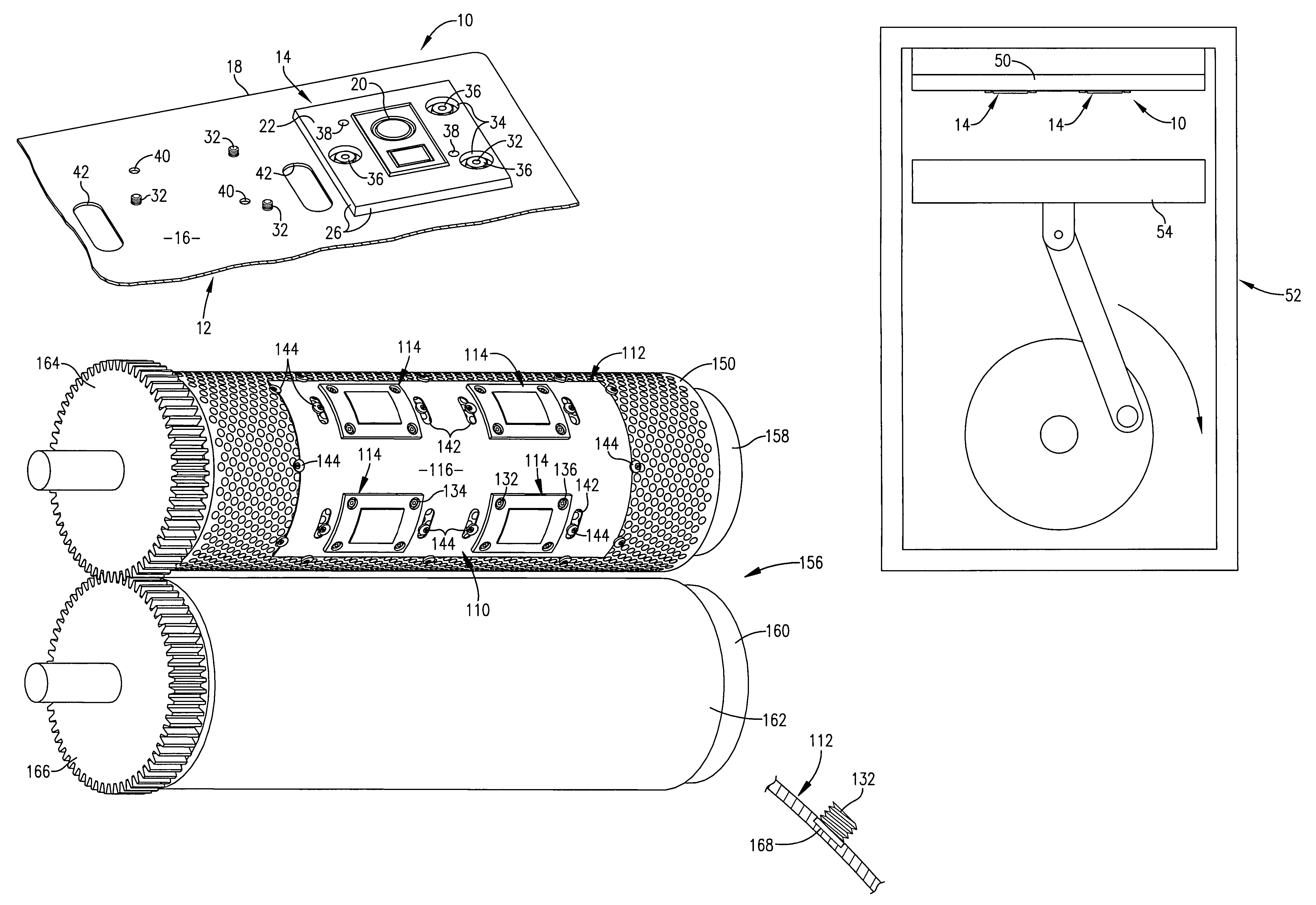
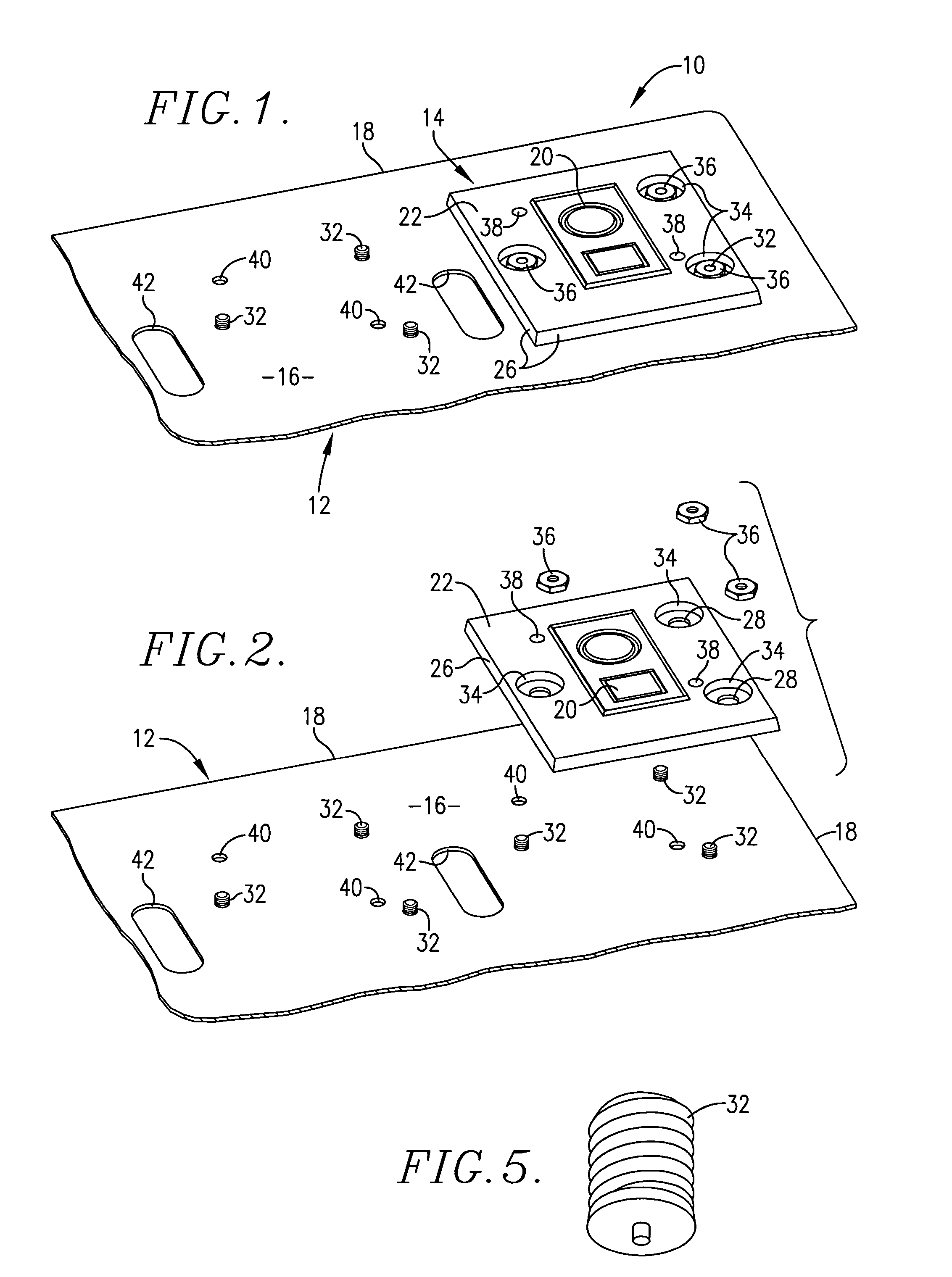
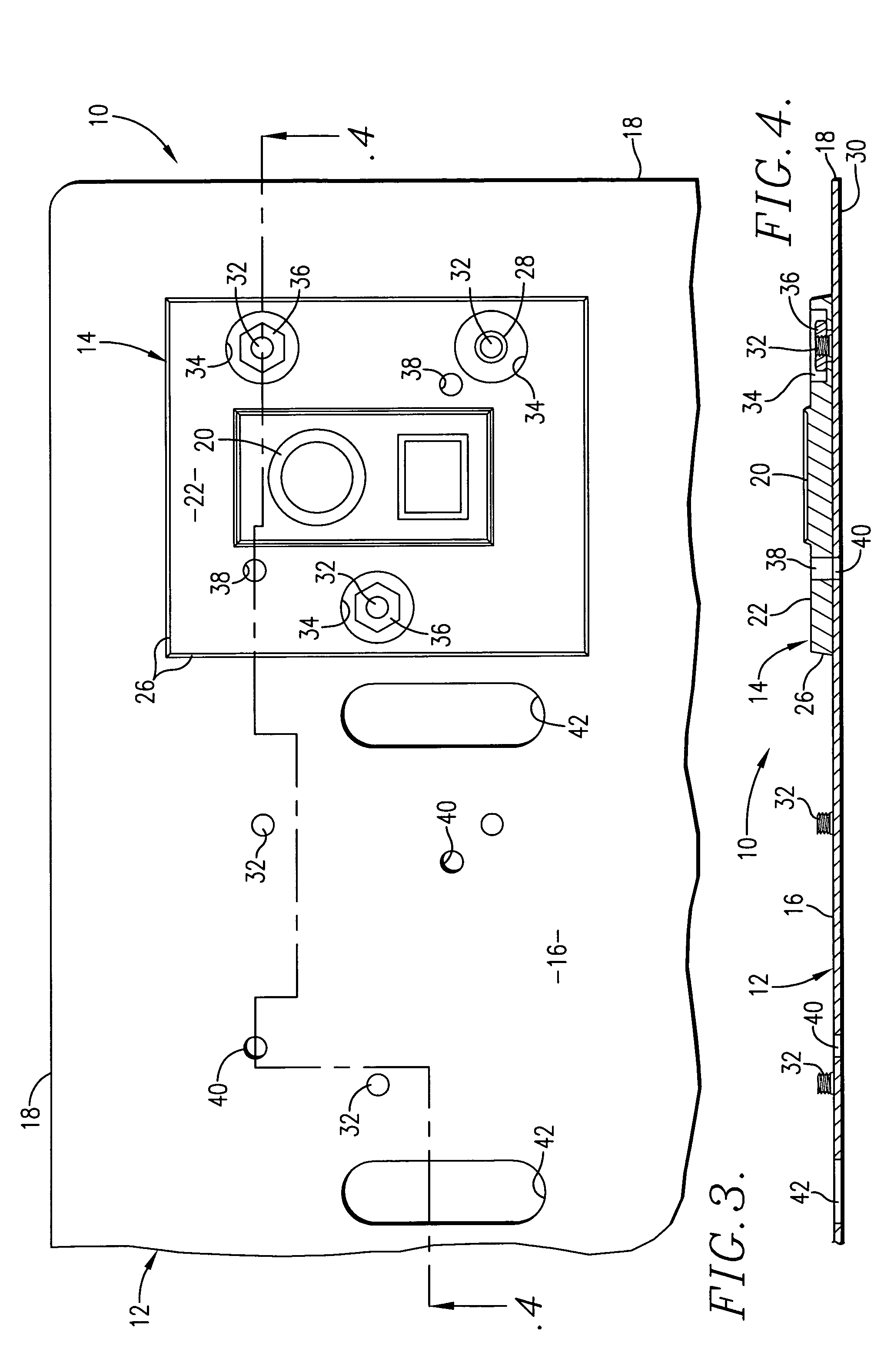
[0072]In accordance with the present invention the support member 12 is preferably a steel plate in which the die receiving surface 16 has been shaved in a milling machine such that the plate thickness is from about 0.030 in. to about 0.100 in. thick, more preferably from about 0.040 in. to about 0.090 in., and most preferably 0.060 in. The thickness of the die plate 14 should be in the range of from about 0.150 in. to about 0.220 in., more preferably from about 0.160 in. to about 0.210 in. and most preferably about 0.190 in. The overall thickness of assembly 10 is most preferably about 0.250 in., in order to comply with industry practice in North America that a foil stamping, embossing or die cutting plate should be no more than about 0.250 in. thick. In the instance of foreign press operations, the total overall thickness of assembly 10 should typically be no more than about 7 mm. in accordance with foreign foil stamping, embossing and die cutting industry practice. In lieu of bei...


PUM

PropertyMeasurementUnit
thicknessaaaaaaaaaa
timeaaaaaaaaaa
thicknessaaaaaaaaaa

Abstract

A graphic arts die and support plate assembly is provided that is adapted to be mounted as a unit on the chase of a flat bed or rotary graphic arts press. The assembly includes a plurality of spaced individual dies fixedly mounted in predetermined relative relationship on a support plate member of the unit. Alignment holes in each die that register with orifices in the support plate member are adapted to receive temporary alignment pins thereby assuring correct positioning of the dies with respect to one another on the support plate member until the dies are affixed to the support plate member. Makeready and die lock-up time of the press is significantly decreased because all dies of the assembly may be preregistered with a design artwork before mounting of the die and support assembly on the press. A series of graphic arts die units are also provided that are adapted to be mounted as an assembly encompassing more than 180° of the circumference of a rotary press chase. The graphic arts die units have die support plate members that may be aligned with indicia on the press chase, and that have notch structure receiving a tool for facilitating alignment and spacing between adjacent die support plate members. Cutouts in the die support plate members permit manual selective shifting of a die relative to the die support plate member therefor using a tool received in a cutout and engageable with the die.

Description

RELATED APPLICATION[0001]This application is a continuation-in-part of U.S. patent application Ser. No. 10 / 851,715, filed May 21, 2004 now abandoned, entitled COMBINATION GRAPHIC ARTS DIE AND SUPPORT ASSEMBLY, incorporated herein by reference.FIELD OF THE INVENTION[0002]This invention relates to a graphic arts die and support assembly adapted to be mounted as a unit on the platen chase of a flat bed graphic arts press or the chase for the cylinder of a rotary graphic arts press. Each of the dies is fixedly mounted in predetermined relative relationship on a die carrier or mounting plate serving as a support member for the dies. A number of arcuate die carrier plates are provided in instances where the curved die carrier plates and associated curved dies are to be mounted on the cylinder of a rotary graphic arts press in disposition such that the assembly of die plates and dies may extend more than 180° around the circumference of the cylinder. Furthermore, each die may be moved slig...

Claims


Application Information

Patent Timeline
Patent Type & Authority Patents(United States)
IPC IPC(8): B21K5/12B26D7/26B26F1/44B21D37/00B23P15/40B31F1/07B41F19/06B41F27/04
CPCB23P15/406B26D7/2614B26D7/2628B31F1/07B41F27/04B41F19/06B26D2007/2607B31F2201/0733B31F2201/0753B31F2201/0776B31F2201/0702Y10T83/9464Y10T83/9466Y10T83/9478
Inventor HUTCHISON, LARRYSMITH, DEREK
Owner UNIVERSAL ENGRAVING
Why Eureka
Try Eureka