Coating edge control

Inactive Publication Date: 2006-08-29
3M INNOVATIVE PROPERTIES CO
View PDF34 Cites 23 Cited by
  • Summary
  • Abstract
  • Description
  • Claims
  • Application Information

AI Technical Summary

Benefits of technology

[0012]In another embodiment, an edge material can be used as a physical boundary against which coating material is coated, to form a desired coating material edge and a desired thickness profile at the coating material edge. The edge material and the barrier material are preferably immiscible. The result can be an improved thickness profile at the edge of the coating material, including an improved shape of the coating material edge. This embodiment can also improve winding of the coated material in the region of the coating material edge, due to an improved thickness profile. This embodiment not only covers up a tapered coating material edge, but can in fact work to improve the shape of the edge and the thickness profile at the edge of the coating material itself.
[0019]Another aspect of the invention relates to a method of coating a substrate with a coating material. The method generally includes providing a substrate, coating edge material onto the substrate using a coater that is a slotted die coater and that is not a curtain coater, and using the same slotted die coater to coat a coating material onto the substrate. The edge material and the coating material contact each other, and the thickness profile of the coating material edge is improved relative to a thickness profile of a coating material edge produced without the edge material.

Problems solved by technology

Films coated onto webs often suffer from different thickness across the width of the film, especially at the coated film edge.
Undesirable results of a tapered edge will result with the particular effect being dependent on the application that the coated material is designed for.
In batteries constructed of multiple wound or stacked layers, undesirable possibilities of an uneven or tapered edge result upon placing the coated substrates into a layered configuration.
This edge effect results in a non-uniform charge density, may cause hot-spots or shorts in the battery, and can ultimately result in a reduced cycle life.

Method used


Image

  • Coating edge control
  • Coating edge control
  • Coating edge control

Examples


example 1

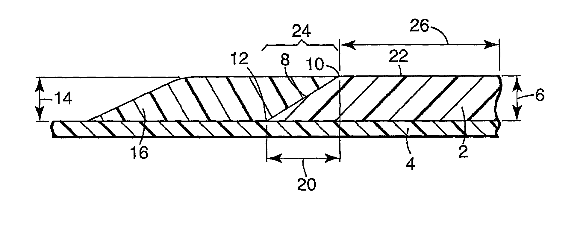
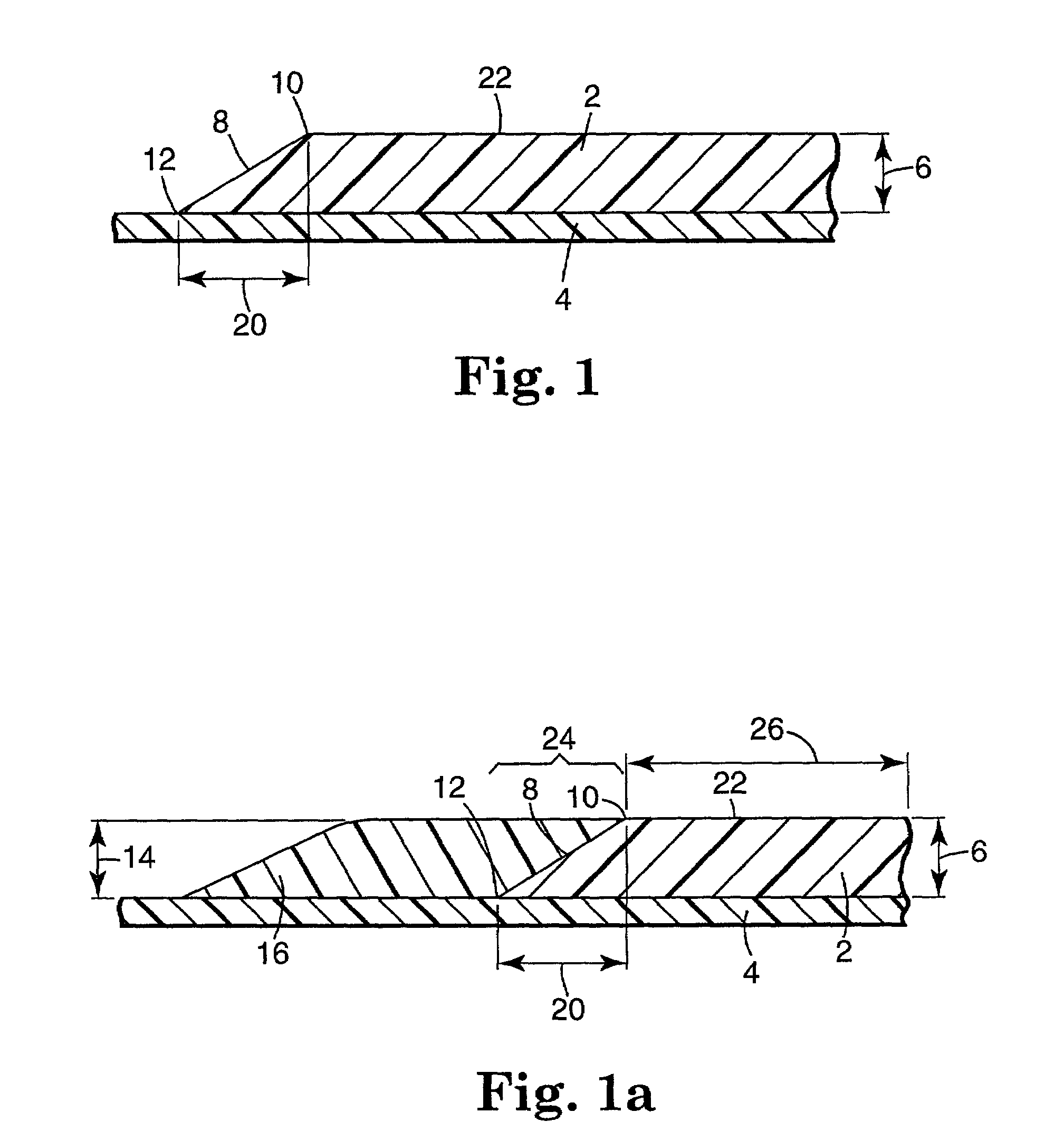
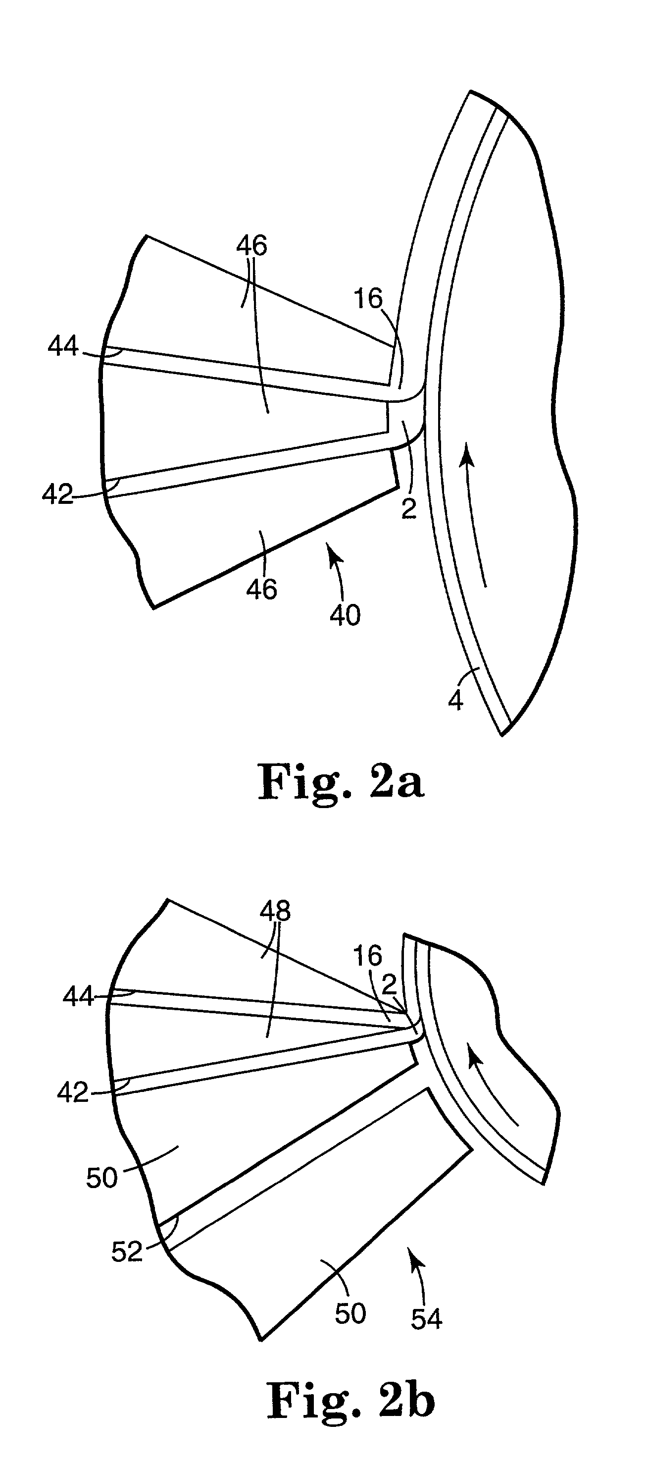
[0110]A die (as described in WO95 / 29763 and additionally illustrated in FIG. 2b) with 2 cavities was used to coat edge barrier strips on either side of a primary coating in a continuous manner. Coatings were placed onto a 1.4 mm polyester backing.

[0111]Shims for each slot of a dual slot coater (as designated in FIG. 2b) were prepared so that openings allowed an edge of a non-active edge material to align with an edge of a cathode material (in this case active) coating to be delivered separately to the web via each of the two slots. The two coatings were coated in different orders in producing different samples, sometimes the cathode material being coated first and sometimes the edge material being coated first.

[0112]For the edge material, 21% (w / w) polyethyleoxide (Polyox WSR-N-80 MW 200.000, Union Carbide) was mixed with a solvent blend of 80% acetonitrile and 20% toluene (w / w).

[0113]For the coating (in tbis case cathode) material, the following composition, 30% w / w in 80:20 aceton...

example 2

[0117]Alternating stripes of Indicator Composition B (“indicator stripe”) at 38% solids and Barrier PSA Composition (“PSA stripe”) at 39% solids were coated onto an untreated, low-haze, 1.4-mil polyester PET transparent film backing using an extrusion die. The basic die is as described in WO95 / 29763 with two separate manifolds and slots for supplying the Composition B (Bottom Manifold) and the Barrier PSA (Top Manifold). A precision gear pump was used to supply the PSA composition to the top manifold and another precision gear pump was used to supply the indicator composition to the bottom manifold. Each pump could be adjusted independently to control flow rate of the compositions to the die. The pump flow rates were set for 2.6 mil wet for the indicator stripe, and 2.9 mil wet for the Barrier PSA Edge. An arrangement of shims allowed distribution and delivery of the Barrier PSA Edge material (1 inch width) adjacent to the Indicator Composition B material (0.5 inch width). Different...

example 3

[0119]Thin film coatings can be prepared by essentially solventless extrusion of mixtures of solid ingredients. The ingredients are intimately mixed by a variety of methods and melted and compressed through a flat orifice to produce a thin coating on a substrate.

[0120]A cathode containing an active material such as V2O5, electrically conductivity material such as carbon black, an electrolyte salt such as lithium trifluoromethanesulfate, and an ionically conductive polymer binder such as polyethylene oxide would be mixed in proportions similar to example #1 but with no solvent or liquid add. The mixture would be fed to a single screw extruder with a temperature sufficient to melt the polymer binder. The mixture would be pumped under pressure by the internal action of the extruder to a flat exit orifice. The melted mixture would be formed and cooled on a web moving past the orifice.

[0121]A second mixture would be prepared from a polymer or monomer binder. The binder may contain additi...


PUM

PropertyMeasurementUnit
Fractionaaaaaaaaaa
Widthaaaaaaaaaa
Widthaaaaaaaaaa

Abstract

Described are methods and products prepared from the methods, each of which include methods of coating certain materials onto a substrate, including coating a coating material and an edge material onto the substrate in a manner which may provide an improved thickness profile of the overall coating, and that may do so by using the edge material to augment the thickness of the coating material edge, or that may do so by improving the coating material edge by using the edge material to affect the shape of the coating material edge, the products being useful, for example, in electrochemical cells.

Description

FIELD OF THE INVENTION[0001]The invention relates to coating methods that include techniques of controlling edge thickness and profile, and products prepared from those methods.BACKGROUND[0002]Coated webs are used in a multitude of commercial and consumer products. A single example is batteries, some of which are constructed from a web coated with a conductive material and wound into a roll or stacked into a number of laminated layers. See, e.g., U.S. Pat. No. 5,360,684, among others.[0003]Films coated onto webs often suffer from different thickness across the width of the film, especially at the coated film edge. If no effort is made to control the thickness or cross-sectional profile of the edge, an edge of a coated material will generally taper off in a gradual slope from the thickness of the bulk coating, to zero thickness.[0004]Undesirable results of a tapered edge will result with the particular effect being dependent on the application that the coated material is designed for...

Claims


Application Information

Patent Timeline
IPC IPC(8): H01M4/04B05D5/00H01M2/08H01M2/14H01M4/66H01M10/40H01M6/18H01M4/131H01M4/1391H01M6/40H01M10/02H01M10/04H01M10/052H01M10/0565H01M10/0585H01M10/36
CPCH01M2/08H01M4/0402H01M4/0404H01M4/0411H01M4/0435H01M4/131H01M4/1391H01M6/40H01M10/0436H01M10/0486H01M10/052H01M10/0585H01M4/04Y10T29/49115H01M6/181H01M6/188H01M10/0565Y02E60/122Y02E60/10Y02P70/50
Inventor DUDLEY, WILLIAM R.MILLER, ALAN P.YAPEL, ROBERT A.
Owner 3M INNOVATIVE PROPERTIES CO
Why Eureka
Try Eureka