Continuous electroforming process to form a strip for battery electrodes and a mandrel to be used in said electroforming process

Inactive Publication Date: 2006-08-29
DSL DRESDEN MATERIAL INNOVATION
View PDF11 Cites 7 Cited by
  • Summary
  • Abstract
  • Description
  • Claims
  • Application Information

AI Technical Summary

Benefits of technology

[0009]It is the object of the invention to provide a continuous electroforming process of high p

Problems solved by technology

However, the discontinuous process claimed there is limited to a production of individual grids on

Method used


Image

  • Continuous electroforming process to form a strip for battery electrodes and a mandrel to be used in said electroforming process
  • Continuous electroforming process to form a strip for battery electrodes and a mandrel to be used in said electroforming process

Examples


Example

EXAMPLE

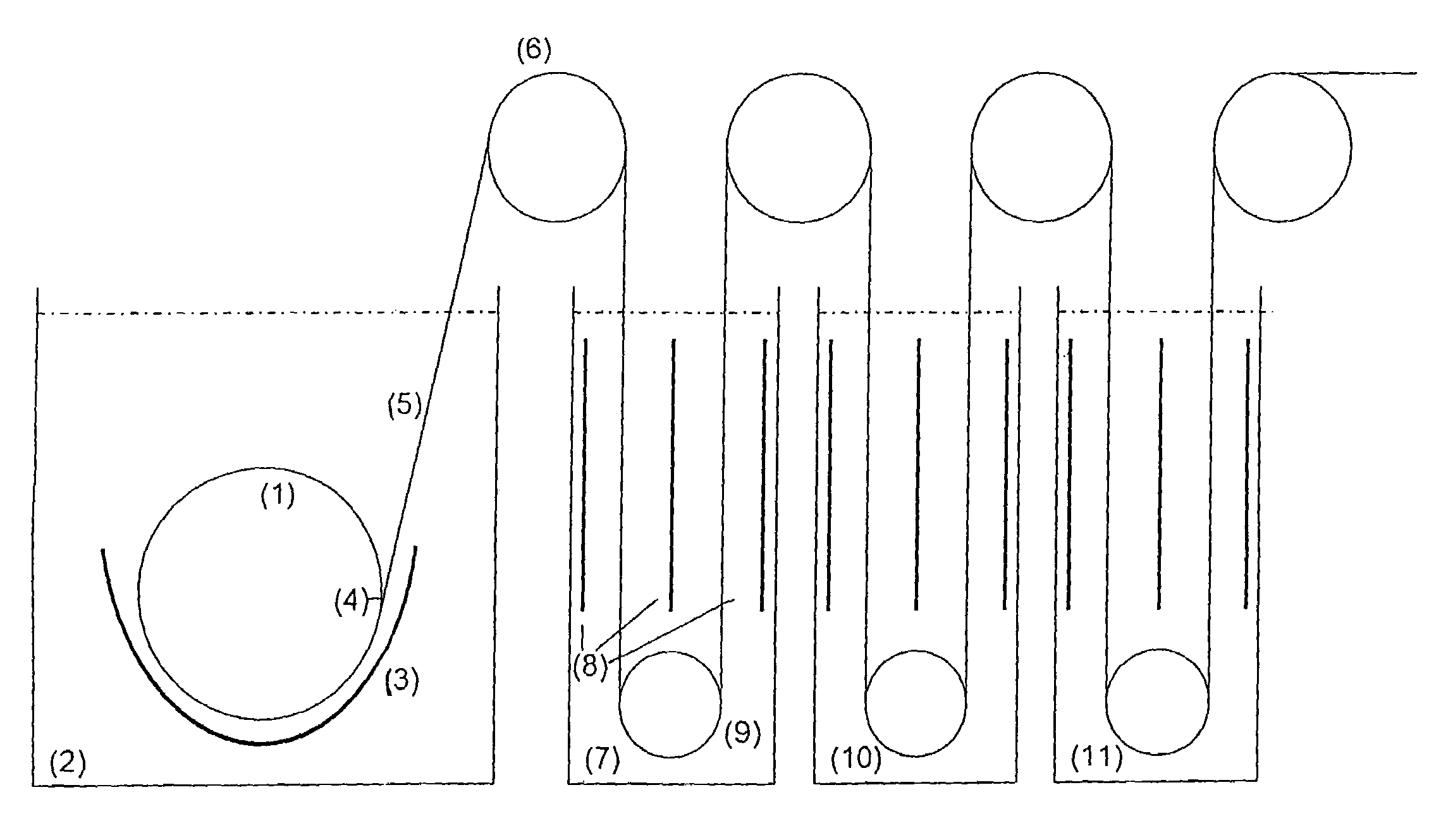
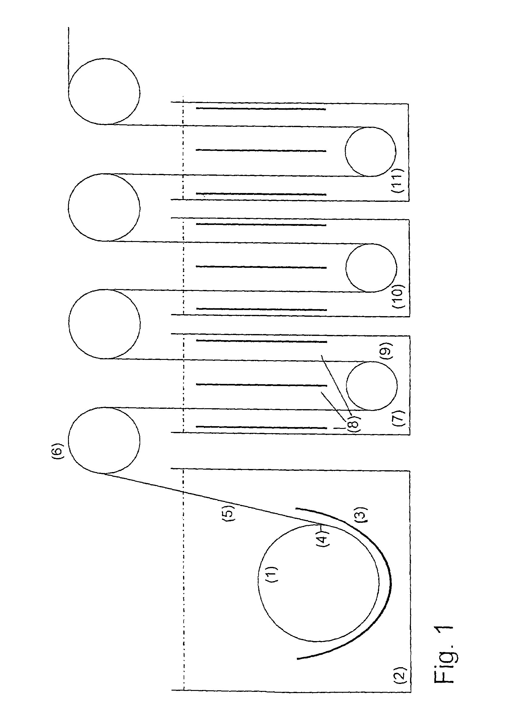
[0023]To produce battery grids having a size of 15 cm×15 cm and a grid area fraction of 50% of the grid size, the surface of a cylinder serving as the mandrel having a diameter of 1 m and a length of 1.2 m is provided with conductive areas corresponding to the grid structure. The cylinder is submerged into an electrolyte as disclosed in DE 44 04 817 C1 and rotates with a circumferential velocity of 106.8 m / h. The electrodeposition occurs at the surface of the cylinder at a current density of about 80 A / dm2. A lead grid strip forms on said cylinder and is separated therefrom upon reaching a layer thickness of 80 μm. Subsequently the strip is transferred to a second electrolyte bath having an effective length of 33 m and is brought to the desired final thickness of 0.5 mm by electrodeposition on both surfaces of the strip at a current density of 20 A / dm2. The production rate is 95 grids per minute.

[0024]The features disclosed in the foregoing description, in the claims and / or i...


PUM

PropertyMeasurementUnit
Current densityaaaaaaaaaa

Abstract

A continuous electroforming process to form a strip for battery electrodes, comprising the steps of providing a mandrel having on its surface a reusable pattern subdivided into conductive and non-conductive areas; moving said mandrel through an electroforming bath to deposit a metal layer on said mandrel while it moves through the electroforming bath until the metal layer has assumed the shape of the conductive pattern and a thickness at least sufficient to provide strength for the layer to be removed from said mandrel; and separating said layer from said mandrel; is characterised by moving said strip through at least one subsequent bath in which electrodeposition of metal takes place on both sides of said strip while it is moved through said subsequent bath, applying a current density of at least 10 A/dm2 and up to 300 A/dm2 to the conductive surface of the moving mandrel and to the metal surface of the strip in each of the subsequent baths; and directing a forced flow of electrolyte onto the surface of the layer and said strip, wherein the reusable conductive pattern of the surface of the mandrel takes the form of at least one battery electrode and the electrolyte contains additives providing increased hardness, increased corrosion resistance and being suited specifically to permit combining a high rate of deposition with controlled surface roughness and controlled composition of the deposit.

Description

BACKGROUND OF THE INVENTION[0001]The invention relates to a continuous electroforming process to form a strip for battery electrodes, comprising the steps of providing a mandrel having on its surface a reusable pattern subdivided into conductive and non-conductive areas; moving said mandrel through an electroforming bath to deposit a metal layer on said mandrel while it moves through the electroforming bath until the metal layer has assumed the shape of the conductive pattern and a thickness at least sufficient to provide strength for the layer to be removed from said mandrel; and separating said layer from said mandrel. The invention further relates to a mandrel to be used in the electroforming process. The present invention is concerned specifically with the continuous production of electrodes, preferentially in foil and grid form, by electroforming, and with obtaining products of specified optimal properties.[0002]DE 44 04 817 C1 describes a process to manufacture battery grids b...

Claims


Application Information

Patent Timeline
IPC IPC(8): H01M10/44C25D1/04C25D1/00C25D1/08H01M4/04H01M4/64H01M4/74
CPCC25D1/04C25D1/08H01M4/74H01M4/0452H01M4/64H01M4/0438Y02E60/10C25D1/00
Inventor WARLIMONT, HANS
Owner DSL DRESDEN MATERIAL INNOVATION
Why Eureka
Try Eureka