Motor driving system having power semiconductor module life detection function

a technology of life detection and motor driving, which is applied in the direction of motor/generator/converter stopper, dynamo-electric converter control, instruments, etc., can solve the problems of reducing the endurance of power cycles and heat cycles, affecting the separation of wires in a large way, and difficult to predict the separation tim

Inactive Publication Date: 2006-08-29
FANUC LTD
View PDF17 Cites 5 Cited by
  • Summary
  • Abstract
  • Description
  • Claims
  • Application Information

AI Technical Summary

Benefits of technology

[0011]According to the invention, there is provided a motor driving system including a power semiconductor module having a built-in means for predicting the separation of the main circuit wire, whereby the approach of the separation time of the main circuit wire can be predicted. As a result, the time to replace the power semiconductor module used in the power devices such as the motor driving system is clarified thereby to prevent the operation failure of the motor driving system.
[0016]According to the invention, the connection strength with the electrode is set lower for the dummy wire than for the main circuit wire. The wires are separated in the ascending order of connection strength. The dummy wire set at a low connection strength, therefore, is separated before the main circuit wire thereby to positively predict the separation of the main circuit wire before the actual separation thereof.
[0026]The soldering conditions may include the soldering area and the soldering length. By setting the dummy wire to a small soldering area and / or a short soldering length, the connection strength of the dummy wire can be decreased.
[0027]The motor driving system according to the invention comprises a detection means to detect the connection condition between the dummy wire and the electrode. The detection means outputs a detection signal through a photo coupler. This detection signal indicates that the dummy wire arranged in the power semiconductor module has been separated from the electrode, and therefore the separation of the main circuit wire from the electrode can be predicted. This prediction, in turn, makes it possible to determine and manage the time of replacing the power semiconductor module.
[0029]The motor driving system can predict the separation of the main circuit wire by detecting the separation of the dummy wire. It is therefore possible to prevent the motor drive operation failure by replacing the power semiconductor module beforehand.
[0030]According to this invention, the separation of the main circuit wire can be predicted. Also, the operation failure of the power semiconductor module and the motor driving system using the power semiconductor module which otherwise might be caused by the separation of the main circuit wire can be prevented.

Problems solved by technology

Thus, the wire is liable to be separated or otherwise damaged at the connection boundary, thereby posing the problem of a reduced endurance to power cycles and heat cycles (See Japanese Unexamined Patent Publication No. 2003-303845, for example).
Therefore, the separation of the wire is affected considerably by the actual operation of the user and the time of separation is difficult to predict.
In the case where the load actually imposed is heavier than the assumed load or power cycle, on the contrary, the power semiconductor chip may be damaged before being replaced at the time of expiry of the calculated service life.

Method used


Image

  • Motor driving system having power semiconductor module life detection function
  • Motor driving system having power semiconductor module life detection function
  • Motor driving system having power semiconductor module life detection function

Examples


Embodiment Construction

[0044]Embodiments of the invention are described in detail below with reference to the drawings.

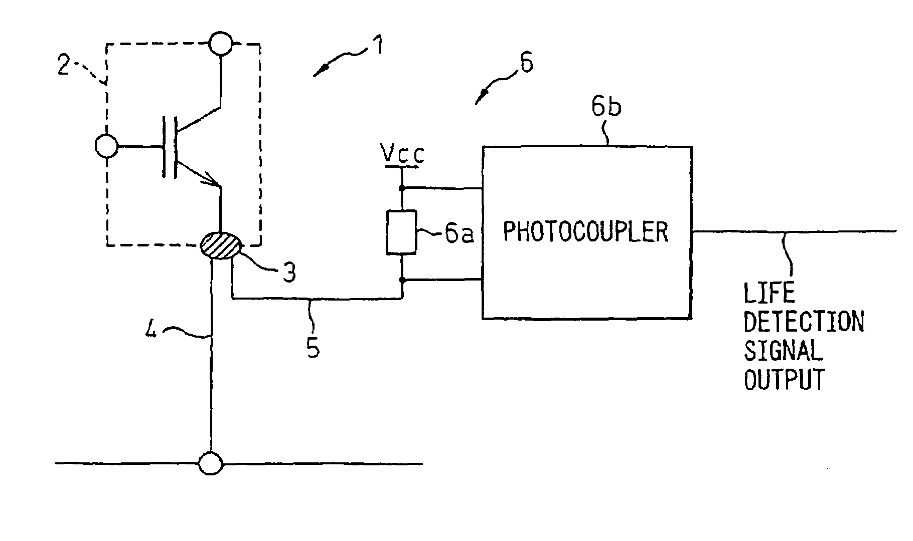
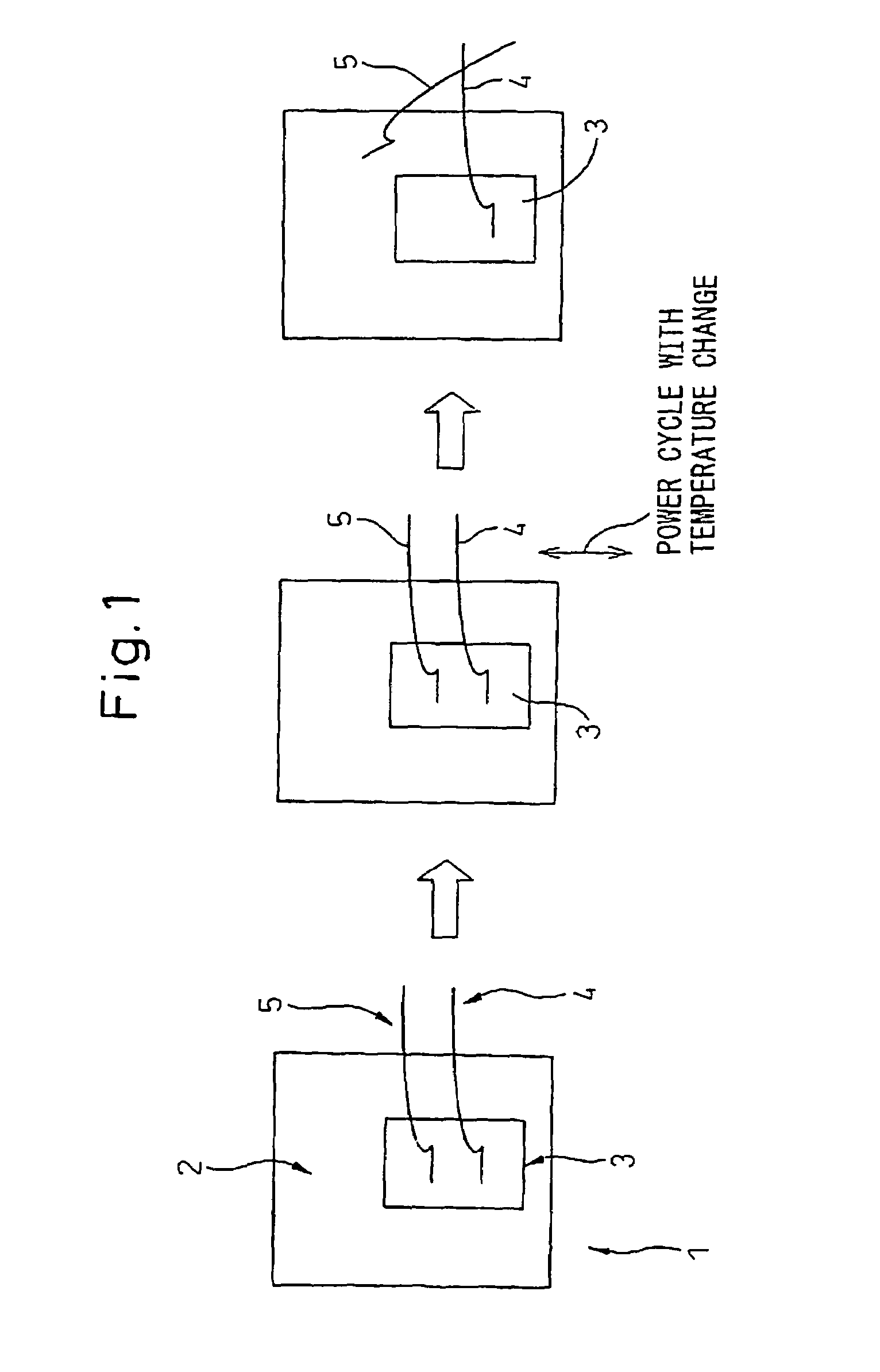
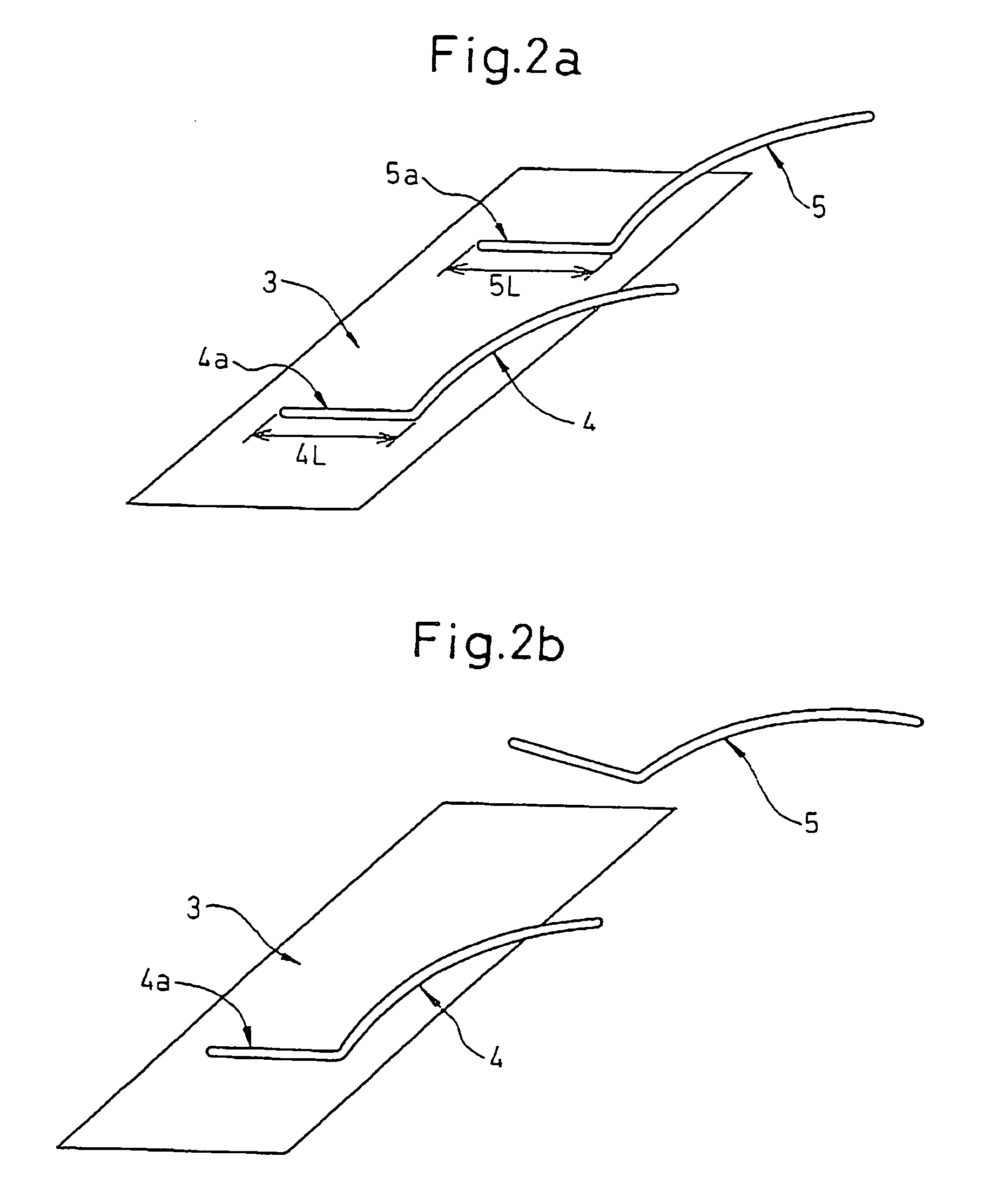
[0045]FIG. 1 is a diagram for explaining the outline of a power semiconductor module of a motor driving system according to the invention. In FIG. 1, a power semiconductor chip 2 includes an electrode 3 for connecting the wires. The electrode 3 is connected with a main circuit wire 4 to supply power between the power semiconductor chip 2 and external devices and a dummy wire 5 to predict the separation of the main circuit wire 4. The circuit is so configured that the dummy wire 5 has no effect on the energizing of the main circuit wire 4 and, even in the case where the dummy wire 5 is separated from the electrode 3, the energizing of the main circuit wire 4 is not adversely affected.

[0046]The connection strength of the connecting portion between the dummy wire 5 and the electrode 3 is set lower than that of the connecting portion between the main circuit wire 4 and the electrode 3. In the...


PUM


Abstract

In the motor driving system, a unit to predict the separation of the wire is built into the power semiconductor module thereby to predict that the time of separation of the wire is approaching before the actual separation of the wire. Thus, the time to replace the power semiconductor module used for power devices such as the motor driving system is clarified to prevent an operation failure of the motor driving system from occurring. The power semiconductor module (1) has a power semiconductor chip (2) mounted thereon, and the power semiconductor chip (2) includes a main circuit wire (4) and a dummy wire (5) connected to the electrode (3) of the power semiconductor. The dummy wire is set to a lower connection strength than the main circuit wire.

Description

BACKGROUND OF THE INVENTION[0001]1. Field of the Invention[0002]The present invention relates to a motor driving system, for driving a motor, using a power semiconductor module formed, by wiring, on a power semiconductor chip.[0003]2. Description of the Related Art[0004]A drive circuit, to drive a power device such as a motor, employs a power semiconductor module having a power semiconductor chip to control the drive current. The power semiconductor module having the power semiconductor chip controls the drive current by being energized intermittently. After the long intermittent energizing operation, the difference in the coefficient of linear expansion between the electrode and the wire, etc. and the repeated sharp temperature change during the drive operation combine to generate a thermal stress in the wire connection boundary. Especially, the larger wire diameter, the larger wire rigidity so that a conspicuous thermal stress in the wire connection boundary is generated. Thus, th...

Claims


Application Information

Patent Timeline
Patent Type & Authority Patents(United States)
IPC IPC(8): G01R31/34G01R31/28H01L25/07H01L21/60H01L23/52H01L25/18
CPCG01R31/2884H01L24/49H01L2924/13091H01L2224/45144H01L2924/014H01L2224/4903H01L2224/49051H01L2924/01004H01L2924/01005H01L2924/01006H01L2924/01033H01L2924/01079H01L2924/01082H01L2924/3011H01L2224/4847H01L2924/00H01L2224/45015H01L2924/351H01L2224/85207H01L24/45H01L2924/14H01L24/48H01L2924/00014
Inventor MATSUBARA, SHUNSUKEHORIKOSHI, SHINICHIMAKITA, HAJIME
Owner FANUC LTD
Why Eureka
Try Eureka