Microcomputer, electronic equipment and debugging system

a debugging system and microcomputer technology, applied in the direction of digital transmission, synchronisation signal speed/phase control, instruments, etc., can solve the problems of large number of pins on the probe, difficult to design the target system, and reduced memory area available for users, so as to achieve the effect of increasing the memory area freely used by users and reducing the size of instruction code in the monitor program for executing the processing in the first monitor

Inactive Publication Date: 2006-08-29
SEIKO EPSON CORP
View PDF16 Cites 27 Cited by
  • Summary
  • Abstract
  • Description
  • Claims
  • Application Information

AI Technical Summary

Benefits of technology

[0020]According to the present invention, the size of instruction code in the monitor program for executing the processing in the first monitor means can highly be reduced. Thus, the memor...

Problems solved by technology

However, this CPU-switching ICE has disadvantages in that there is a large number of pins on the probe 306 and also a large number of lines 308 of the probe 306.
It is also difficult to design the target system 300.
This CPU-switching ICE also has problems in that, if a different microcomputer is used, even if it is a modified version thereof, it is necessary to use a debugging tool of a different...

Method used


Image

  • Microcomputer, electronic equipment and debugging system
  • Microcomputer, electronic equipment and debugging system
  • Microcomputer, electronic equipment and debugging system

Examples


Embodiment Construction

[0047]A preferred embodiment of the present invention will now be described in detail with reference to the drawings.

1. Characteristics of this Embodiment

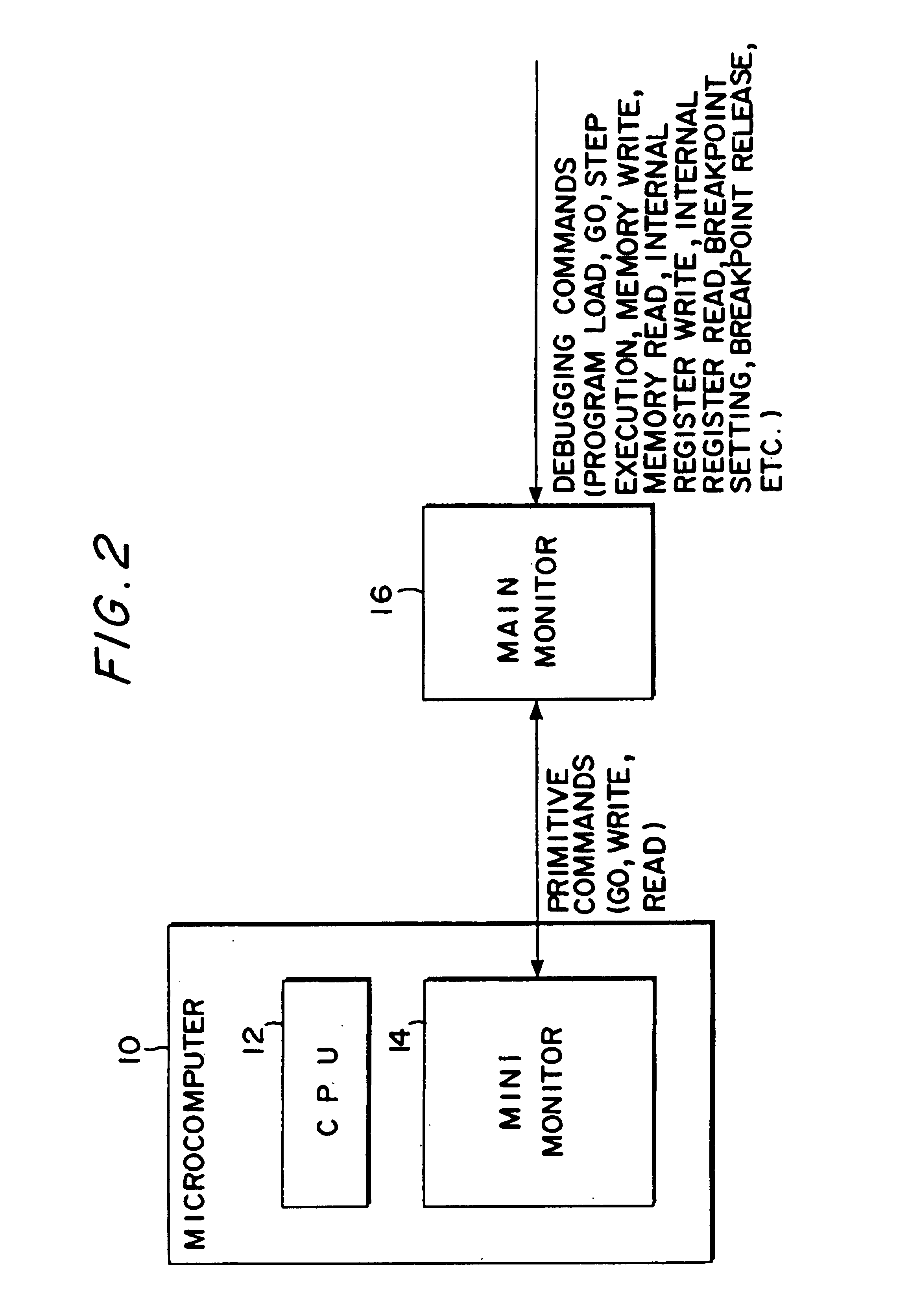
[0048]The features of this embodiment will first be described with reference to FIG. 2.

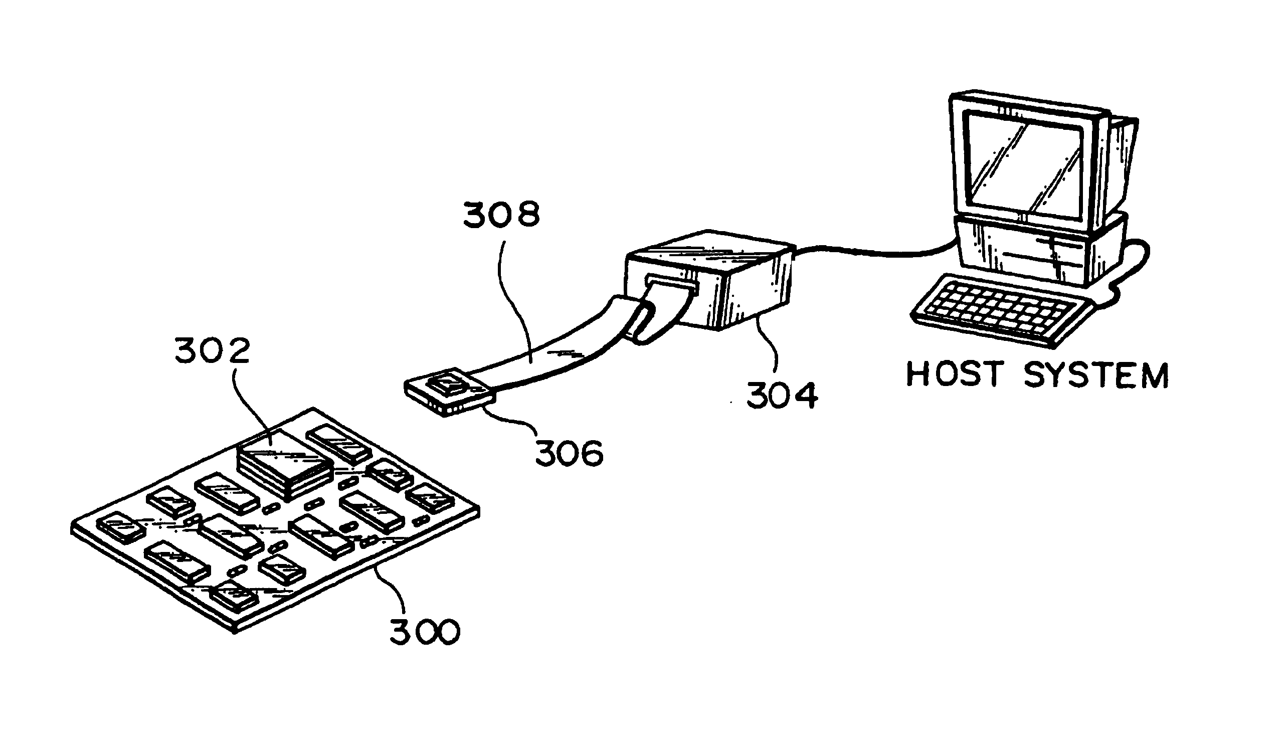
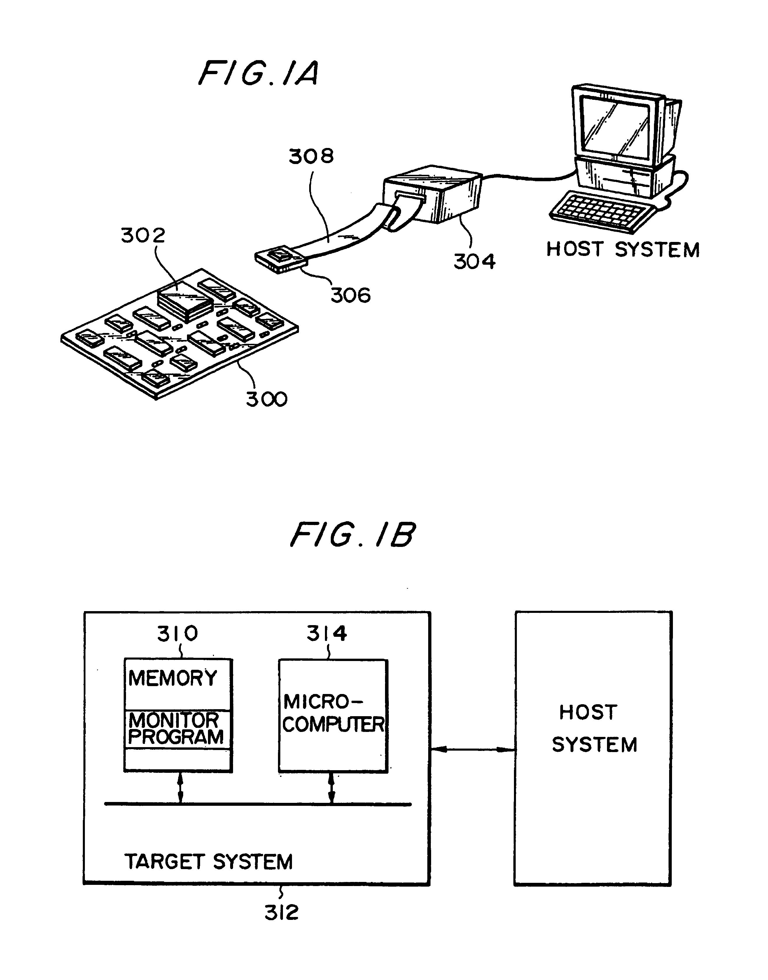
[0049]Referring to FIG. 2, a microcomputer 10 according to the embodiment of the present invention comprises a central processing unit (CPU) 12 and a mini monitor section (first monitor means) 14 that is the primary part of this embodiment. Outside the microcomputer 10 is provided a main monitor section (second monitor means) 16 which performs processing to convert (decompose) a debugging command issued by a host system, for example, into a primitive command. The mini monitor section 14 transfers data to and from the main monitor section 16. The mini monitor section 14 determines the primitive command to be executed based on the data received from the main monitor section and performs the processing to execute the primitive command.

[0050]The debu...


PUM


Abstract

An object is to provide a microcomputer, electronic instrument and debugging system which can realize an on-chip debugging function through a reduced size of instruction code or a reduced circuit scale. A main monitor section (16) converts a debugging command into a primitive command. A mini monitor section (14) transfers data to and from the main monitor section (16) to execute a primitive command determined based on the receive data. The primitive commands include go, write and read commands. A control register having its address allocated on a memory map in the debugging mode is provided together with a mini monitor RAM. The mini monitor section (14) serving as a slave is connected to the main monitor section (16) serving as a master through a half-duplex bidirectional communication line so that transfer data can be fixed-length. The receive data includes a command identifying data. A mini monitor program has been stored in a ROM. The mini monitor section (14) and main monitor section (16) use a clock in common to generate a sampling clock while transferring data in the start-stop synchronization.

Description

TECHNICAL FIELD[0001]The present invention relates to a microcomputer and also to electronic equipment and a debugging system comprising the same.BACKGROUND ART[0002]There has recently been increasing demand for the incorporation of microcomputers that are capable of implementing high-level information processing into electronic equipment such as game machines, car navigation systems, printers, and portable information terminals. Such a thus-incorporated microcomputer is usually mounted on a user board called a target system. A software development support tool called an in-circuit emulator (ICE) is widely used for supporting the development of software to be used in the target system.[0003]The CPU-switching (swapping) type of ICE shown in FIG. 1A is the most common type of this kind of ICE used in the art. With this CPU-switching ICE, a microcomputer 302 is removed from a target system 300 during debugging, and a probe 306 of a debugging tool 304 is connected thereto instead. This ...

Claims


Application Information

Patent Timeline
IPC IPC(8): G06F11/00G06F11/22H04L7/04G06F11/273G06F11/28G06F15/78H04L1/22
CPCG06F11/273G06F11/3656G06F11/3648
Inventor KUDO, MAKOTOHIJIKATA, YOICHI
Owner SEIKO EPSON CORP
Why Eureka
Try Eureka