Eureka AIR delivers breakthrough ideas for toughest innovation challenges, trusted by R&D personnel around the world.

Fluid-pressure regulated wafer polishing head

Inactive Publication Date: 2006-09-05
APPLIED MATERIALS INC
View PDF64 Cites 4 Cited by
  • Summary
  • Abstract
  • Description
  • Claims
  • Application Information

AI Technical Summary

Benefits of technology

[0011]In a further aspect of the invention, a retractable and pressure extendable retaining ring assembly extends around the backing member and prevents the wafer from sliding out from below the surface of the substrate backing member. An annular ring extending bladder extends along the backside of the ring, the bladder when pressurized urges the ring against the pad. The force with which the retaining ring is clamped to the polishing pad is dependant on the gas pressure maintained in this bladder.
[0012]These inventive configurations, alone or in combination, provide several advantages. One advantage is direct control of a uniform force on the back surface of the wafer being polished within the perimeter of the seal extending between the holding member and the wafer. A pressure is uniformly maintained without the complication or edge effects of an intermediate bladder in direct contact with the substrate. Another advantage is that the total force pressing the wafer backing member toward the wafer is controlled separately by the force created by controlling the pressure within the bellows completely independent of the influence of the pressure cavity formed between the wafer and the backing member. If the force on the wafer due to the pressure behind the wafer in the wafer facing cavity exceeds the force on the seal to the wafer exerted by the pressure in the bellows then the wafer will lift away from its seal and seal blow-by will occur until equilibrium restores the seal.
[0013]The pressure within the wafer facing cavity controls the distribution pattern by which this total force is transmitted from the wafer backing member to the wafer. Providing a vacuum to the cavity can cause the center of a supported wafer to bow inward, so that only a perimeter polishing contact is achieved. In contrast, positive pressure in excess of the seal contact pressure will cause the wafer to lift off (move away from) the seal and for gas to blow-by (it cannot cause outward bowing of the substrate as the pressure at the center of the substrate can never exceed the pressure at the perimeter of the substrate), and will also cause a uniform pressure on the back of the wafer. The bowing or deflection of the wafer, if any, is controlled and limited by the pressure on the perimeter seal, so long as the internal pressure of the recess or cavity facing the wafer does not exceed the seal pressure and cause seal blow-by.
[0015]The extension and retraction of the wafer retaining ring assembly is independently controlled by the use of the continuous annular bladder positioned around the perimeter of the wafer backing member. Such a configuration can eliminate the pressure variations associated with the point contacts of springs provided to urge the ring into contact with the pad. In one configuration, one or more restoring springs are supported on a rigid portion of the retaining ring backing ring to cause the retaining ring to retract from its lowered position when the extension bladder is depressurized.
[0016]The frictional force between the seal at the perimeter of the wafer backing member is sufficient such that when the polishing head is rotated during polishing while the wafer is in contact with the polishing slurry on the polishing pad, there is sufficient frictional force that the wafer rotates with the polishing head and overcomes the resistance to rotation with the head due to the motion of the pad and the polishing media on the polishing pad.

Problems solved by technology

The spring-loaded retaining rings are subject to bending and torsional deflection due to the spring configuration which does not provide a continuous contact force but provides a series of point loads, clamping the ring to the polishing pad.
This flexing can cause variation in the clearance between the ring and pad which affects the depth of slurry that passes under the ring, and it also affects the pad compression adjacent to the edge of the wafer.
Variations in the depth of polishing slurry and in pad compression adjacent to the edge of the wafer can cause differential polishing of the wafer to the detriment of polishing uniformity.
These prior art configurations as described can introduce polishing variations due to bladder edge effects, non-uniformly distributed force pressing the wafer to the polishing pad, and retaining ring deflections which require close and frequent monitoring to assure satisfactory polishing results.

Method used


Image

  • Fluid-pressure regulated wafer polishing head
  • Fluid-pressure regulated wafer polishing head
  • Fluid-pressure regulated wafer polishing head

Examples


Embodiment Construction

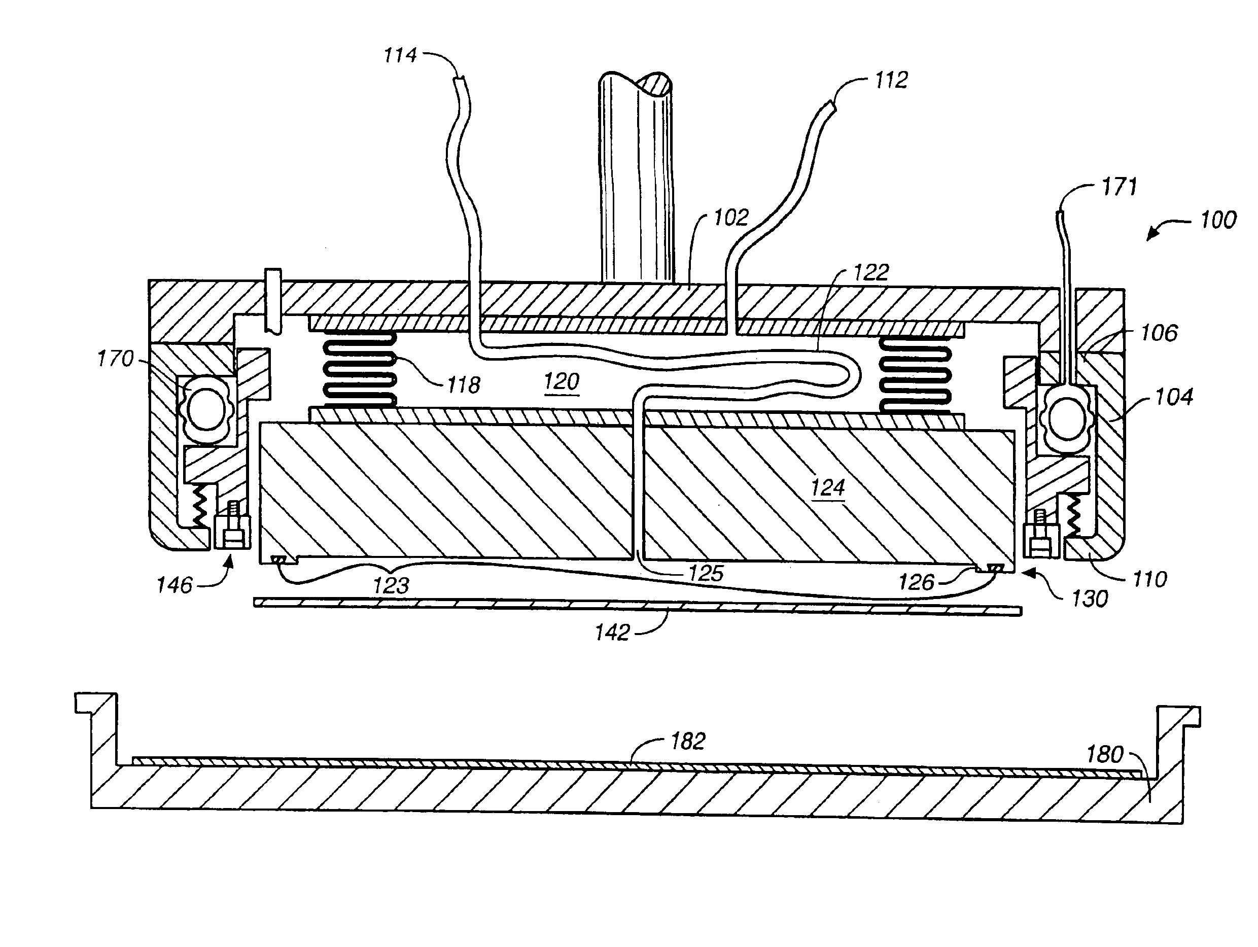
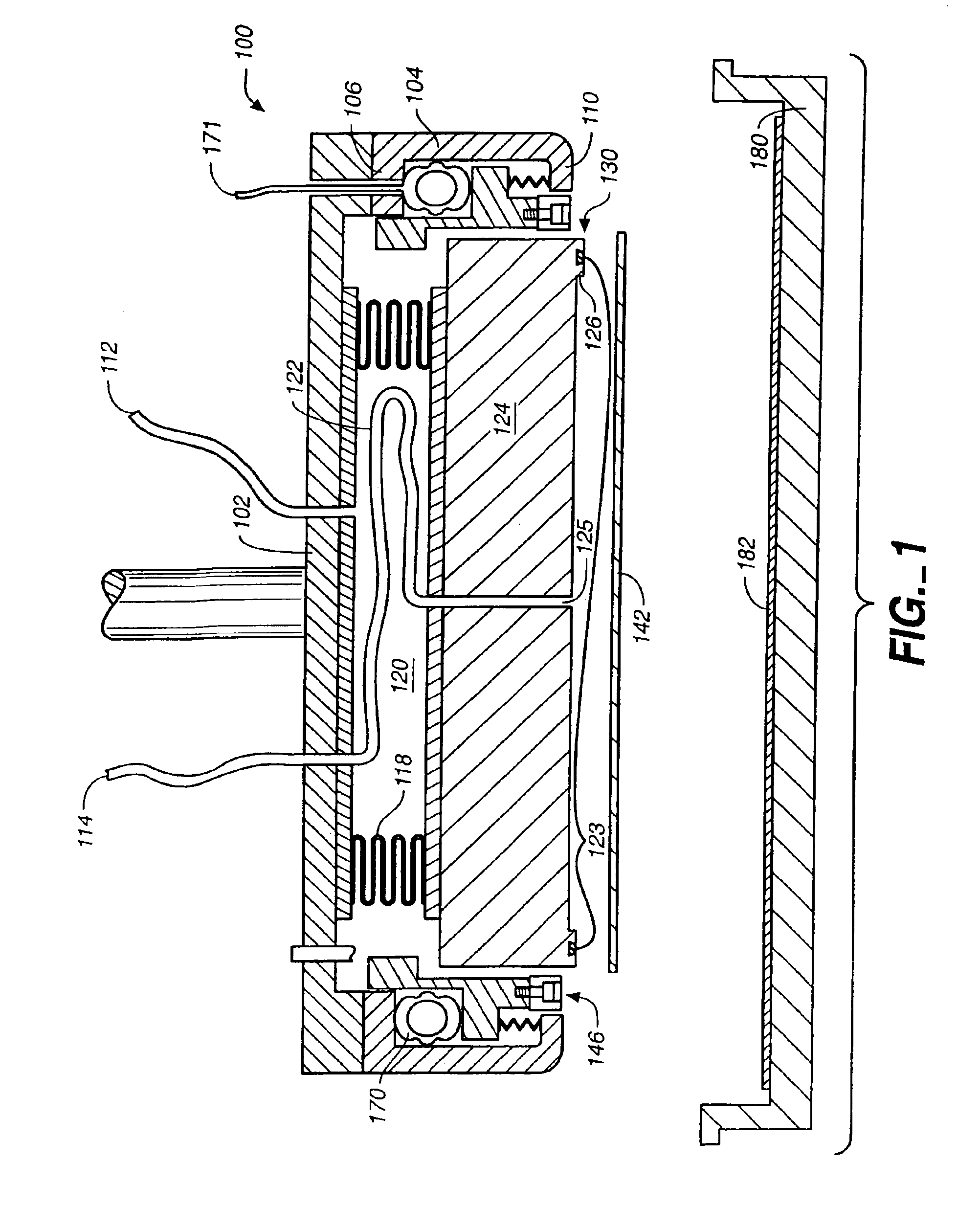
[0020]FIG. 1 shows a polishing head assembly 100 in a configuration according to the invention. The polishing head 100 includes a polishing head housing support plate 102 which is integral with its rod or stem support member. This support plate 102 is generally circular so as to match the circular configuration of the substrate or wafer 142 to be polished. A polishing head housing descending wall 104 is attached to the bottom of the support plate 102 by a descending wall top flange 106. The descending wall 104 includes a lower lip 110 which curves inward toward the wafer 142. The descending wall 104 encloses a wafer perimeter retaining ring assembly 146 enclosing a wafer backing member 124. The wafer backing member 124 is attached to the support plate 102 by a bellows 118 which allows a vertically variable vacuum seal. The bellows 118 encloses a bellows chamber 120. The bellows chamber 120 can be pressurized positively or negatively through a gas passage 112 to which is connected th...


PUM

PropertyMeasurementUnit
Forceaaaaaaaaaa
Pressureaaaaaaaaaa
Areaaaaaaaaaaa

Abstract

A wafer polishing head utilizes a wafer backing member having a wafer facing pocket which is sealed against the wafer and is pressurized with air or other fluid to provide a uniform force distribution pattern across the width of the wafer inside an edge seal feature at the perimeter of the wafer to urge (or press) the wafer uniformly toward a polishing pad. Wafer polishing is carried out uniformly without variations in the amount of wafer material across the usable area of the wafer. A frictional force between the seal feature of the backing member and the surface of the wafer transfers rotational movement of the head to the wafer during polishing. A pressure controlled bellows supports and presses the wafer backing member toward the polishing pad and accommodates any dimensional variation between the polishing head and the polishing pad as the polishing head is moved relative to the polishing pad. An integral, but independently retractable and extendable retaining ring assembly is provided around the wafer backing member and wafer to uniformly and independently control the pressure of a wafer perimeter retaining ring on the polishing ad of a wafer polishing bed.

Description

CROSS-REFERENCE TO RELATED APPLICATIONS[0001]This application is a continuation of U.S. application Ser. No. 10 / 201,428, now U.S. Pat. No. 6,652,368 filed Jul. 22, 2002 which is a continuation of U.S. application Ser. No. 09 / 892,143, filed Jun. 25, 2001 now U.S. Pat. No. 6,443,824, which is a continuation of U.S. application Ser. No. 09 / 406,027, filed Sep. 27, 1999, now U.S. Pat. No. 6,290,577, which is a continuation of U.S. application Ser. No. 08 / 488,921, filed Jun. 9, 1995, now U.S. Pat. No. 6,024,630, each of which are incorporated herein by reference in their entirety.FIELD OF INVENTION[0002]This invention relates generally to mechanical polishing, and in particular to polishing heads used to polish generally circular semiconductor wafers in the semiconductor industry.BACKGROUND OF THE INVENTION[0003]This invention provides improved construction and easier operability of polishing heads useful for positioning a substrate, in particular, a semiconductor substrate, on the surfac...

Claims


Application Information

Patent Timeline
IPC IPC(8): B24B5/00B24B37/30B24B37/32H01L21/304
CPCB24B37/32B24B37/30B24B37/04
Inventor SHENDON, NORMANSHERWOOD, MICHAELLEE, HARRY
Owner APPLIED MATERIALS INC
Why Eureka
Eureka Blog
Learn More