Bi-directional multi-port inverter with high frequency link transformer

a high-frequency link transformer and multi-port technology, applied in the direction of emergency power supply arrangements, process and machine control, emergency supply, etc., can solve the problems of low conversion efficiency from renewable energy sources to battery-to-utility grid, low frequency transformer efficiency, and inability to adapt to the needs of the battery-centric energy system, so as to reduce the limitations of battery-centric energy systems, expand the potential capabilities of power converters, and reduce the effect of power consumption

Active Publication Date: 2006-09-05
SCHNEIDER ELECTRIC SOLAR INVERTERS USA
View PDF14 Cites 93 Cited by
  • Summary
  • Abstract
  • Description
  • Claims
  • Application Information

AI Technical Summary

Benefits of technology

[0002]The invention is a multi-port power electronics topology, with a high frequency transformer as the common power “conduit” and interface point for all ports. This invention would allow for energy systems that are high-frequency-transformer-core-centric as opposed to battery-centric. This invention mitigates essentially all of the limitations of battery-centric energy systems. The underlying power converter concept used for this invention was originally invented by William McMurry and disclosed in U.S. Pat. No. 3,517,300 in 1970. Since then, others have expanded the potential capabilities of these power converters but with less-than-novel or with technically obvious variations on the original McMurry invention. The invention disclosed herein involves a number of novel power circuit topologies that allow much greater port flexibility and provide enhanced performance. The invention allows a port to perform as a boost or buck converter when sourcing power into the high frequency transformer, a capability that has not been previously established. These added capabilities allow applications to be served that would otherwise not have been practical. Also, the invention allows each non-battery port to “see” only the reflected battery characteristics at the transformer interface so that the operation of all non-battery ports are independent and non-interactive. The preferred embodiment of the invention is intended for residential electrical energy systems. There are three ports; a bi-directional battery port that allows a storage battery to source energy to the transformer or sink energy from the transformer to charge the battery, a bi-directional AC port that allows the transformer to source energy to loads and also to sink or source energy from a utility grid at unity power factor, and a renewable energy port that sources energy into the transformer and is capable of controlling the operating point of the renewable energy source and the amount of power delivered into the transformer. Products developed using this invention will be (i) lighter because transformers operating at ultrasonic frequencies are much smaller than line frequency transformers (ii) lower cost because of the smaller transformer and the system-integrated power conversion approach and (iii) more efficient because of fewer power conversion stages and the lower core and copper losses associated with high frequency transformers. These advantages are had without sacrificing the isolation properties of a transformer.

Problems solved by technology

There are a number of inherent limitations with this approach.
This approach requires a heavy, expensive, and typically inefficient, low frequency transformer.
(ii) The conversion efficiency from the renewable energy source to the battery to the utility grid is low because of the additive losses from each successive power conversion stage.
(iii) Higher voltage, higher efficiency, lower cost photovoltaic series “string” arrays are not practical because of the photovoltaic / battery voltage disparity.

Method used


Image

  • Bi-directional multi-port inverter with high frequency link transformer
  • Bi-directional multi-port inverter with high frequency link transformer
  • Bi-directional multi-port inverter with high frequency link transformer

Examples


Embodiment Construction

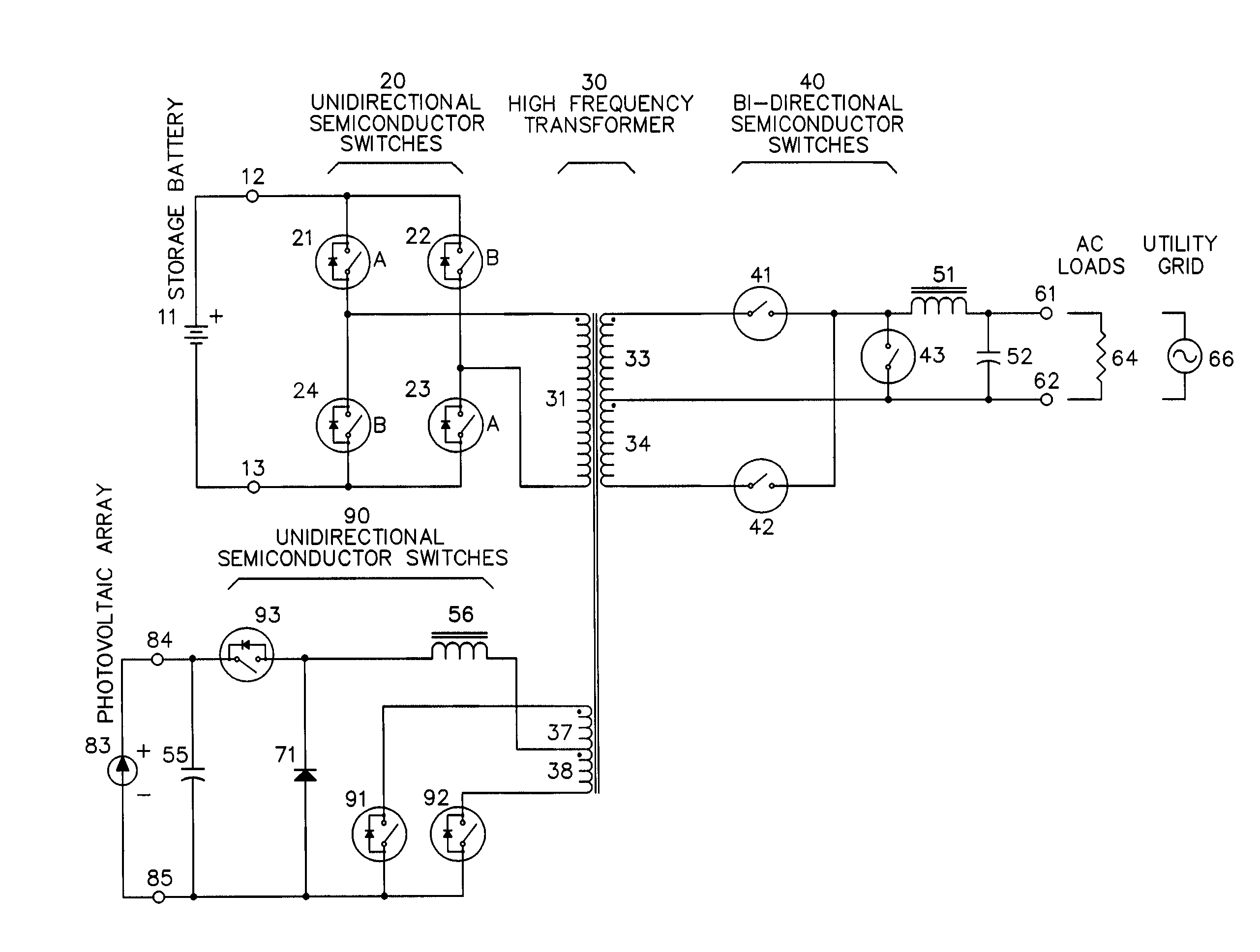
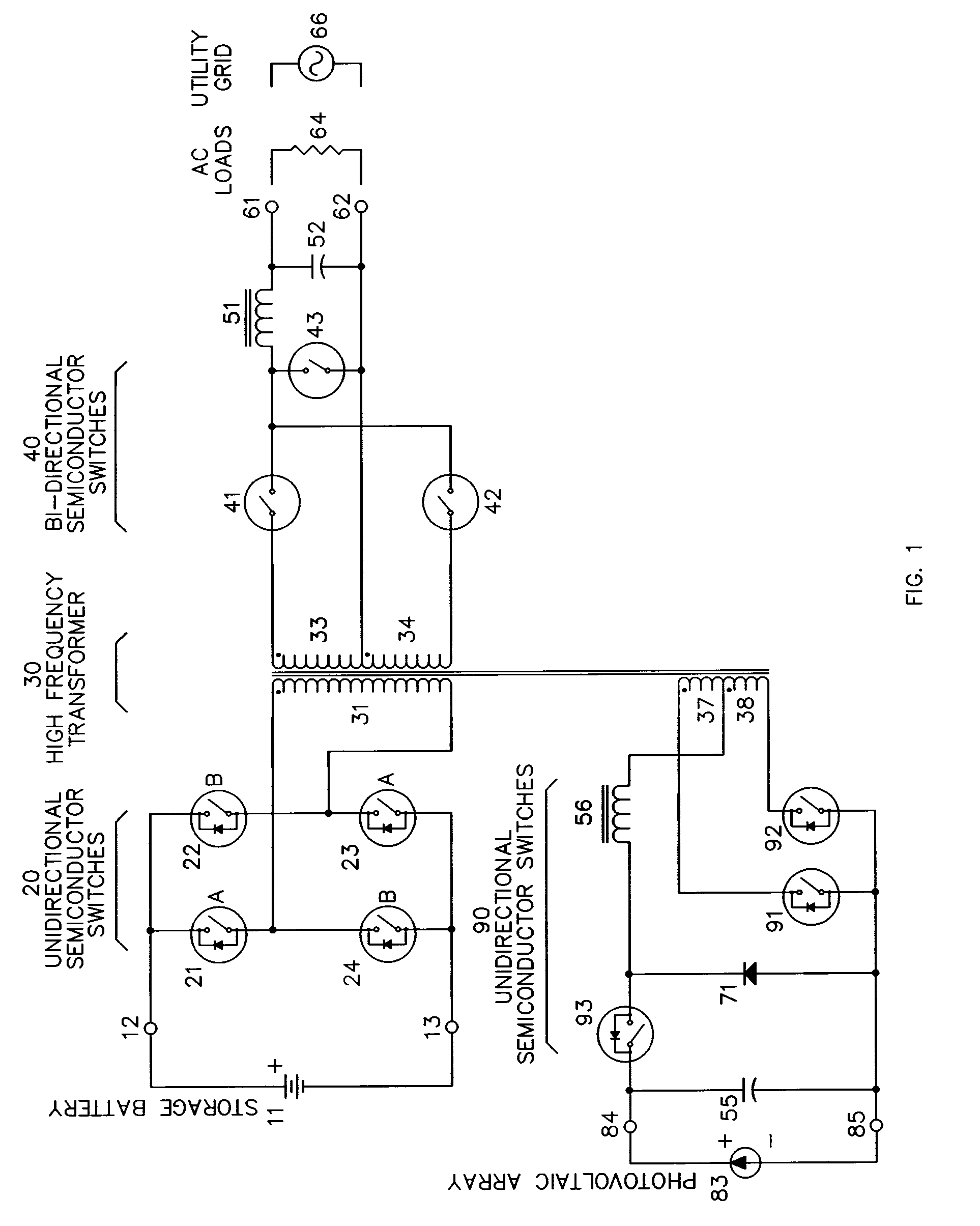
[0011]FIG. 1 illustrates the preferred embodiment of the invention, a three-port power converter topology with one bi-directional battery port, at terminals 12 and 13, one four-quadrant AC port, at terminals 61 and 62, and one unidirectional renewable energy port at terminals 84 and 85. Two types of semiconductor switch elements are shown. Switches 21–24 and 91–93 have unipolar voltage blocking, unidirectional current control and bi-directional current conduction capabilities and are referred to as unidirectional semiconductor switches on all diagrams. Switches 41–43 have bipolar voltage blocking, bi-directional current control and bi-directional current conduction capabilities and are referred to as bi-directional switches in all diagrams. The battery port, at terminals 12 and 13, contains a typical, full-bridge arrangement of power switches 21–24 and is connected to winding 31 of high frequency transformer 30. Switch pairs 21, 23 and 22, 24 are alternately closed and opened at a h...


PUM


Abstract

This invention is a multi-port power converter where all ports are coupled through different windings of a high frequency transformer. Two or more, and typically all, ports have synchronized switching elements to allow the use of a high frequency transformer. This concept and type of converter is known. This invention mitigates a number of limitations in the present art and adds new capabilities that will allow applications to be served that would otherwise not have been practical. A novel circuit topology for a four-quadrant AC port is disclosed. A novel circuit topology for a unidirectional DC port with voltage boost capabilities is disclosed. A novel circuit topology for a unidirectional DC port with voltage buck capabilities is disclosed. A novel circuit for a high efficiency, high frequency, bi-directional, AC semiconductor switch is also disclosed.

Description

BACKGROUND OF INVENTION[0001]The field of this invention is power electronics and electrical power conversion. Electronic power inverters are devices for converting direct current (DC) power, usually from a storage battery, into alternating current (AC) power for household appliances. Some inverters also convert power from an AC source to charge the storage battery used by the inverter. Devices capable of power transfer in either direction, DC-to-AC or AC-to-DC are commonly referred to as inverter / chargers or bi-directional inverters. Inverters are also used in renewable and distributed energy systems to convert DC power from photovoltaic panels, fuel cells or wind turbines into power that can be delivered into the utility grid. There is a growing demand for an inverter product with this capability that can also charge storage batteries and support AC loads when the utility grid is not available. Residential systems with both renewable energy sources and energy storage components ty...

Claims


Application Information

Patent Timeline
Patent Type & Authority Patents(United States)
IPC IPC(8): H02J7/00H02M1/10H02M7/48H03K17/687
CPCH02J7/35H02M7/4807H02M1/10H02J3/387H02J2001/004H02J2009/067Y02B90/14H02M3/3374Y02B10/72H02J2300/30H02J9/067H02J3/381Y02B10/70H02J2300/24H02J3/40Y02E10/56Y02B90/10
Inventor WEST, RICK
Owner SCHNEIDER ELECTRIC SOLAR INVERTERS USA
Why Eureka
Try Eureka