Measuring the 3 dB frequency bandwidth of a phase-locked loop

a phase-locked loop and frequency bandwidth technology, applied in the direction of pulse automatic control, electric devices, etc., to achieve the effect of simple testing procedures, simple and less expensive components

Inactive Publication Date: 2006-09-05
AVAGO TECH WIRELESS IP SINGAPORE PTE
View PDF3 Cites 9 Cited by
  • Summary
  • Abstract
  • Description
  • Claims
  • Application Information

AI Technical Summary

Benefits of technology

[0003]The 3 dB frequency bandwidth (f3 dB) of a PLL is determined by measuring the frequency of a VCO signal when an up charging current is applied, measuring the frequency of the VCO signal when a down charging current is applied, and then using the two frequency measurements to calculate the 3 dB frequency bandwidth of the PLL. In an embodiment, the up and down charging currents are applied through a charge current switch system and the frequency measurements are made with a frequency counter. Both the charge current switch system and the frequency counter are simpler and less expensive components than the phase modulator and the spectrum analyzer that are required by other known techniques for measuring the 3 dB frequency bandwidth. Additionally, the charge current switch system and the frequency counter can be monolithically integrated with the PLL. That is, the functionality needed to support the 3 dB frequency bandwidth measurement can be included “on-chip” with the PLL. Including the switching and frequency counting functionality on-chip is relatively inexpensive and allows for relatively simple testing procedures.

Problems solved by technology

Additionally, the charge current switch system and the frequency counter can be monolithically integrated with the PLL.

Method used


Image

  • Measuring the 3 dB frequency bandwidth of a phase-locked loop
  • Measuring the 3 dB frequency bandwidth of a phase-locked loop
  • Measuring the 3 dB frequency bandwidth of a phase-locked loop

Examples


Embodiment Construction

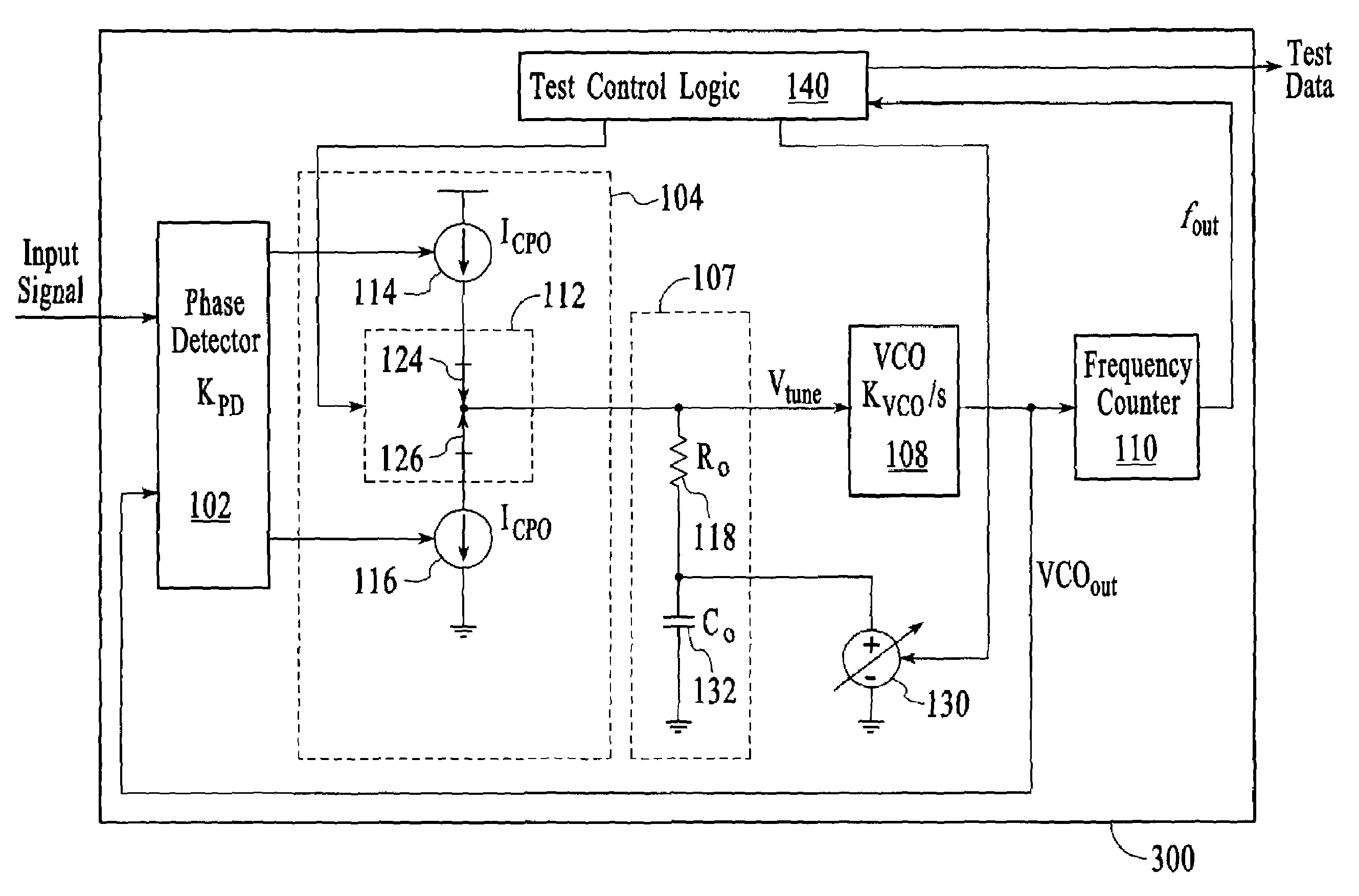
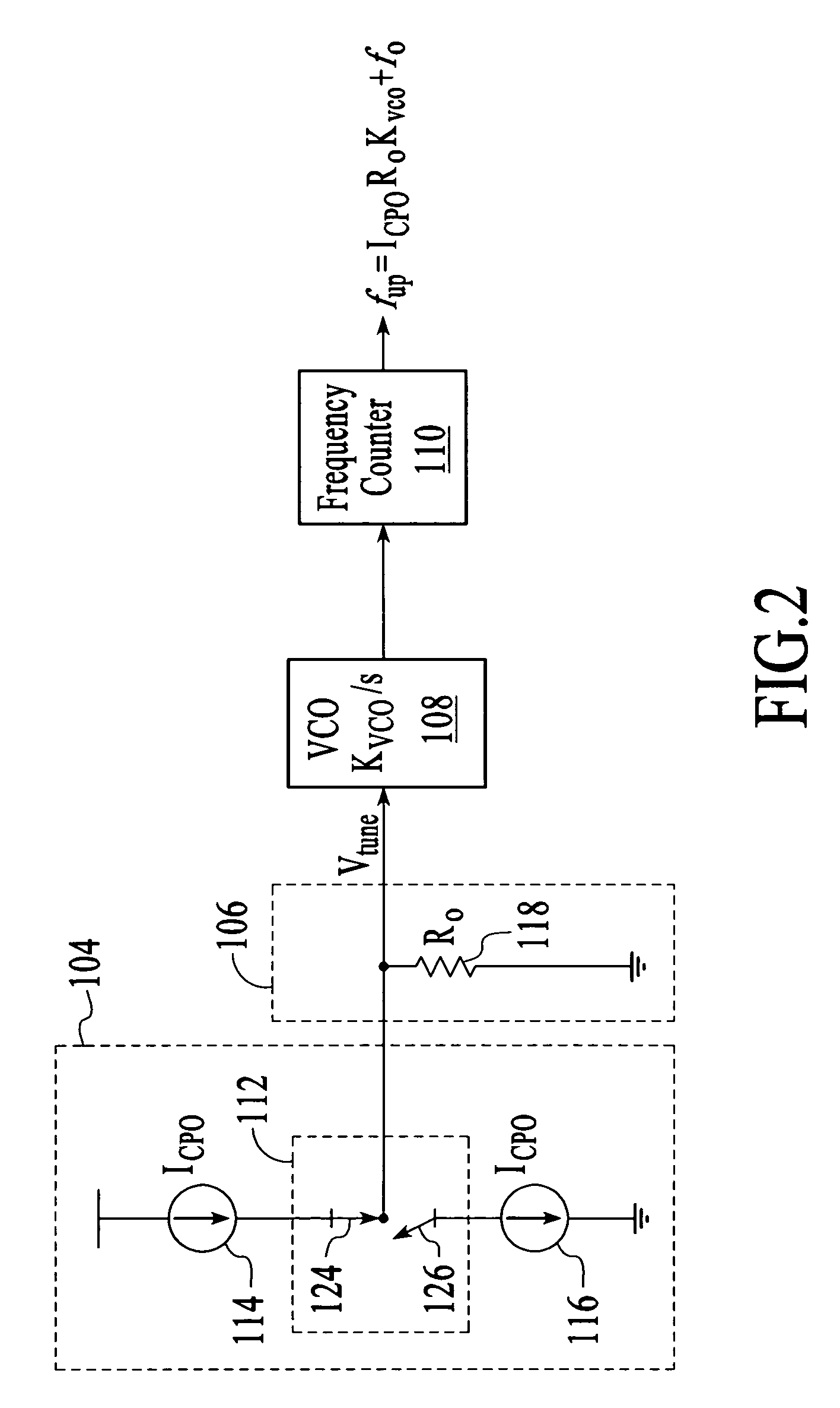
[0018]The task of a phase-locked loop (PLL) is to lock the phase and frequency of a voltage controlled oscillator (VCO) signal to a particular signal, referred to herein as an input signal. In accordance with the invention, the 3 dB frequency bandwidth of a PLL is determined by measuring the frequency of the VCO signal when an up charging current is applied, measuring the frequency of the VCO signal when a down charging current is applied, and then using the two frequency measurements to calculate the 3 dB frequency bandwidth of the PLL.

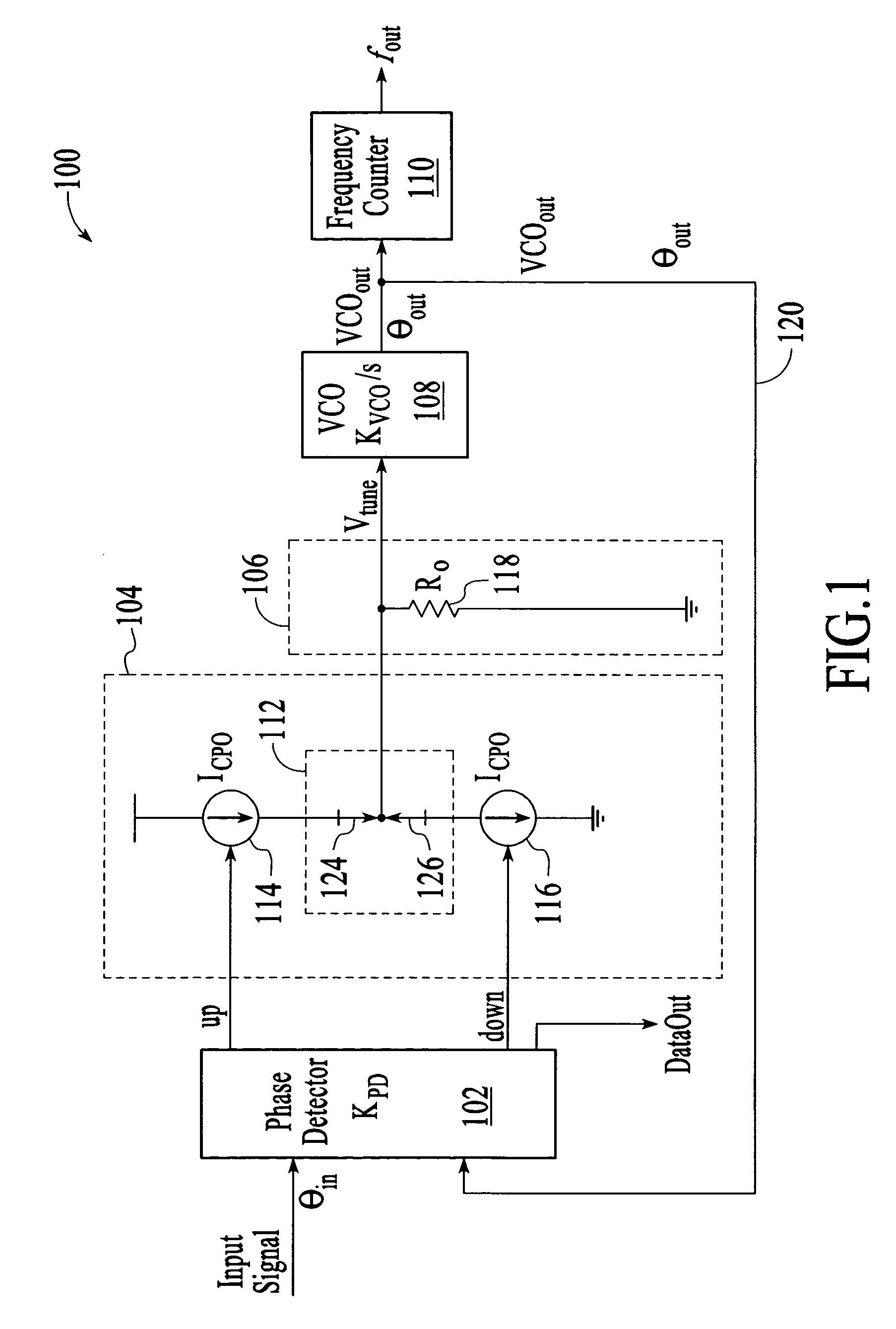
[0019]FIG. 1 depicts an embodiment of a first order PLL 100 that includes a phase detector 102, a charge pump 104, a loop filter 106, and a VCO 108. FIG. 1 also depicts a frequency counter 110 and a charge current switch system 112 that support the measurement of the 3 dB frequency bandwidth of the PLL. The frequency counter and charge current switch system are described in more detail below after a description of the PLL components and operation.

[00...


PUM


Abstract

The 3 dB frequency bandwidth of a phase-locked loop (PLL) is determined by measuring the frequency of a voltage controlled oscillator (VCO) signal when an up charging current is applied, measuring the frequency of the VCO signal when a down charging current is applied, and then using the two frequency measurements to calculate the 3 dB frequency bandwidth of the PLL. The up and down charging currents can be applied through a charge current switch system and the frequency measurements can be made with a frequency counter, both of which are monolithically integrated with the PLL. The technique for measuring the 3 dB frequency bandwidth can be applied to a first order or a second PLL. When applied to a second order PLL, the technique includes an initial frequency centering operation.

Description

BACKGROUND OF THE INVENTION[0001]Phase-locked loops (PLLs) are used in data communications and telecommunications applications to lock onto the frequency and phase of a signal. In particular, PLLs are often used in clock and data recovery (CDR) applications. A typical PLL includes a phase detector, a charge pump, a loop filter, and a voltage controlled oscillator (VCO) that produces a VCO signal. One performance characteristic of a PLL is the 3 decibel (dB) frequency bandwidth. The 3 dB frequency bandwidth is a measure of the frequency bandwidth within which the PLL is able to track frequency changes of the input signal. The 3 dB frequency bandwidth is usually measured directly by phase modulating the input signal and observing the amplitude of the resulting output signal. The frequency at which the ratio of the input signal phase to the output signal phase (θout / θin, commonly known as the closed loop transfer function), drops from unity to −3 dB identifies the 3 dB frequency bandwi...

Claims


Application Information

Patent Timeline
Patent Type & Authority Patents(United States)
IPC IPC(8): H03L7/00H03L7/06
CPCH03L7/0891
Inventor GALLOWAY, BRIAN JEFFREY
Owner AVAGO TECH WIRELESS IP SINGAPORE PTE
Why Eureka
Try Eureka