Open loop resonator filter using aperture

a resonator filter and aperture technology, applied in the field of open loop resonator filters, can solve the problems of too large filter miniaturization, too difficult to implement the saw filter into the high-speed communication system that requires wide bandwidth, and the inapplicability of the saw filter to the broadband system, etc., to achieve superior selectivity characteristics, wide bandwidth, and flat group delay

Inactive Publication Date: 2006-09-05
ELECTRONICS & TELECOMM RES INST
View PDF12 Cites 28 Cited by
  • Summary
  • Abstract
  • Description
  • Claims
  • Application Information

AI Technical Summary

Benefits of technology

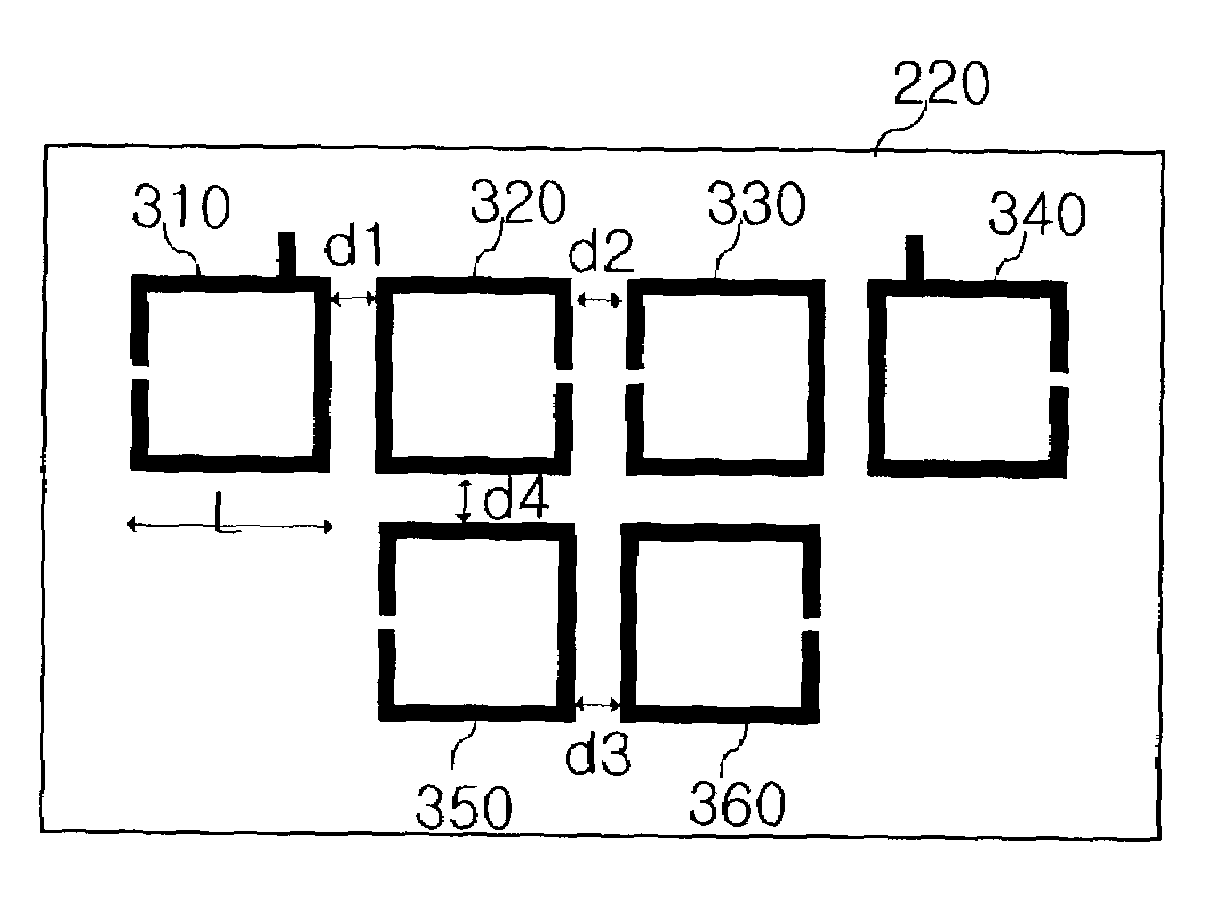
[0018]It is, therefore, an object of the present invention to provide a small size open loop resonator filter structure with wide bandwidth, flat group delay and superior selectivity characteristics by forming an aperture on a predetermined portion of a ground plane.

Problems solved by technology

However, the SAW filter is not applicable to broadband system for bad group delay ripple and narrow bandwidth.
Thus, it is too difficult to implement the SAW filter into the high-speed communication system that requires wide bandwidth.
However, in case the conventional half wavelength type resonator is used for the filter, there is a problem for miniaturization of the filter since multiple layers of the resonator are necessary for high selectivity, small insertion loss and flat group delay characteristics.
However, there is no study been progressed for wideband communication application like a high-speed satellite communication.
However, the pass-band ripple also is large because the difference between two resonant frequencies due to tight coupling is large.
Also, there is a limitation on reducing coupling space between loops for tight coupling.
In case the coupling space between loops is extremely narrow, the sensitivity of the filter can become serious problem and it is difficult to fabricate the filter.
However, in case of reducing the coupling gap between lines and thickness of line in the above mentioned conventional open loop resonator, it causes to increase a ripple of the pass-band.
Also, if the gap becomes extremely narrowed, manufacturing process of a circuit will be very complicated because of a responsiveness of manufacturing.

Method used


Image

  • Open loop resonator filter using aperture
  • Open loop resonator filter using aperture
  • Open loop resonator filter using aperture

Examples


Embodiment Construction

[0027]Other objects and aspects of the invention will become apparent from the following description of the embodiments with reference to the accompanying drawings, which is set forth hereinafter.

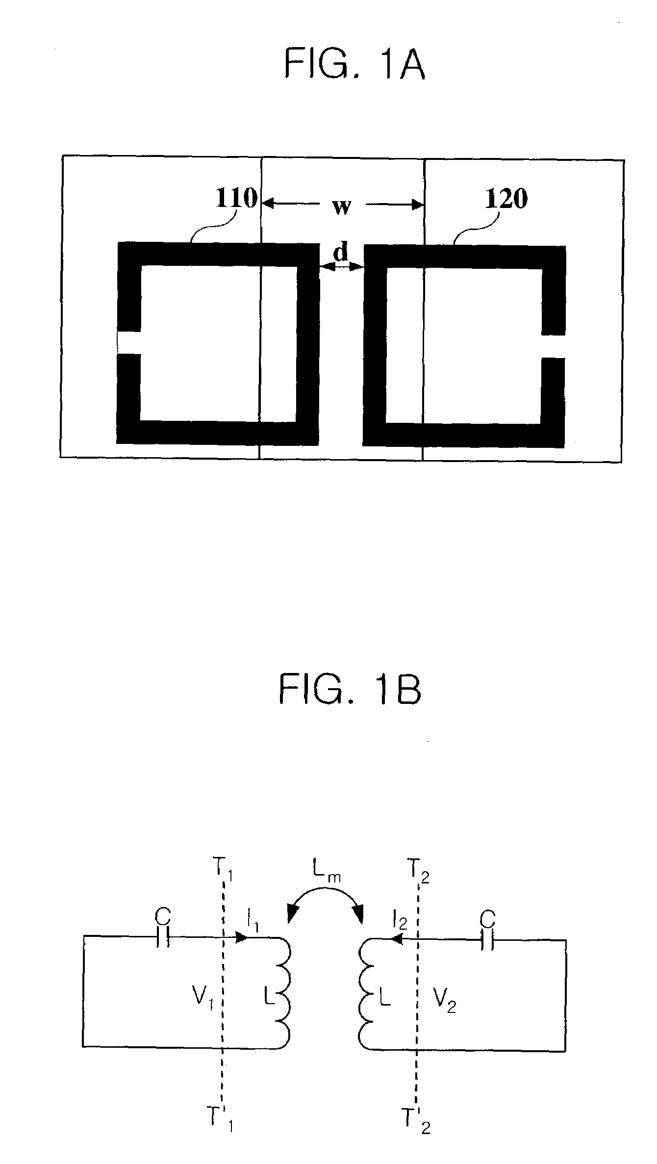
[0028]FIGS. 1A and 1B are a diagram for explaining magnetic coupling of an open loop resonator using an aperture. A circuit of FIG. 1B is an equivalent circuit of FIG. 1A.

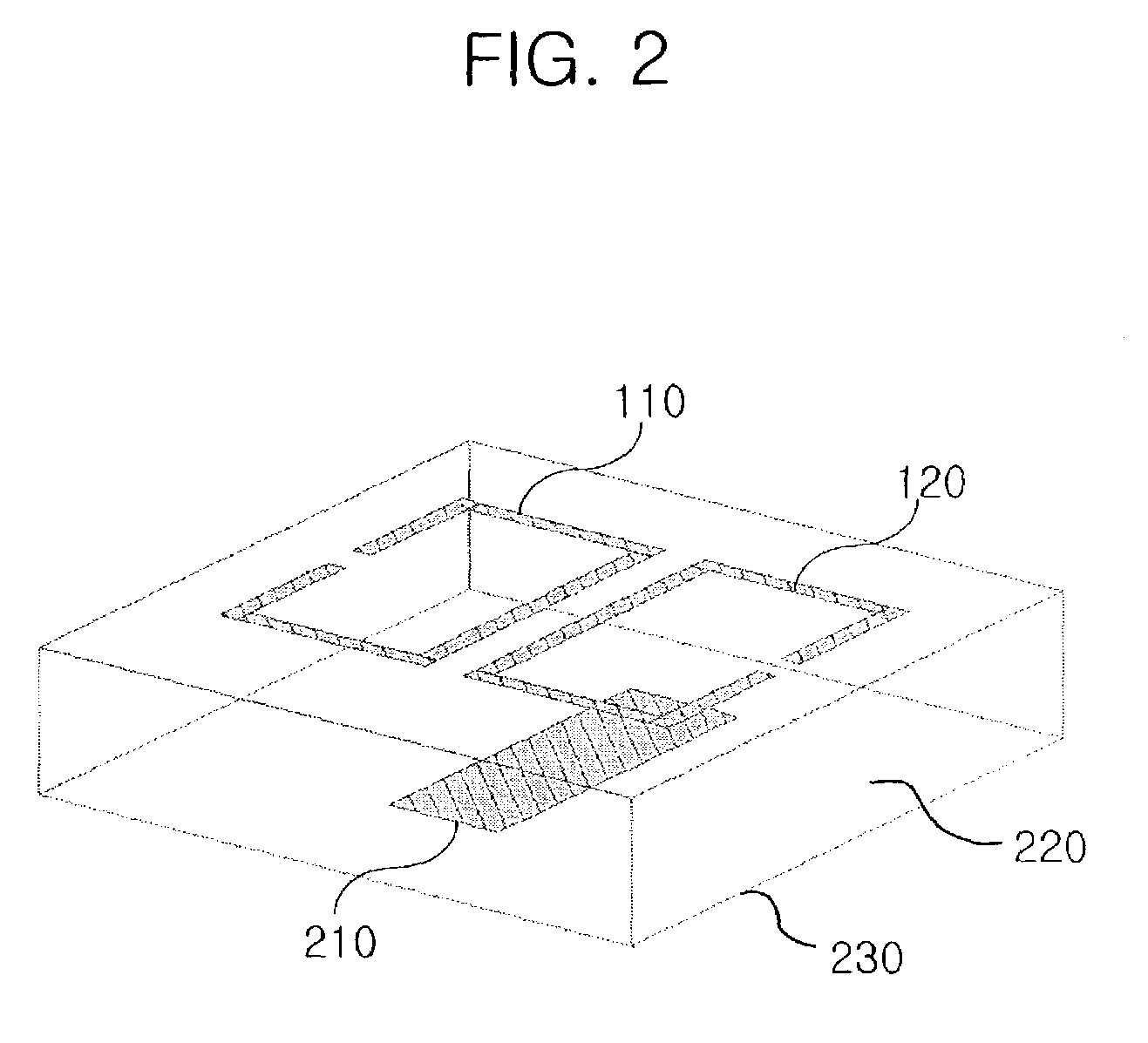
[0029]FIG. 2 is a perspective view of an open loop resonator filter using an aperture in accordance with a preferred embodiment of the present invention.

[0030]As referring to FIG. 2, the open loop resonator filter includes open loop resonators 110 and 120, an aperture 210, a dielectric substrate 220 and a ground plane 230.

[0031]The open loop resonators 110 and 120 are formed by microstrip lines.

[0032]The aperture 210 is formed on a predetermined position of the ground plane 230 and the predetermined position is a downwardly projected position from a position of an upper side where two resonators are faced and a gap couplin...


PUM


Abstract

An open loop resonator filter employed aperture on the ground plane is disclosed. The open loop resonator filter using apertures on the ground plane formed on the dielectric substrate, the open loop resonator filter including: one or more open loop resonators formed on a upper side of the dielectric substrate and implemented by microstrip lines; and one or more apertures formed on a predetermined area of the ground plane. The present invention can control the coupling coefficient of the open loop resonator without degrading the group delay characteristics by forming the aperture on the ground plane. Therefore, by forming the aperture on the ground plane, it is possible to design a filter having a wide bandwidth characteristic.

Description

FIELD OF THE INVENTION[0001]The present invention relates to an open loop resonator filter using an aperture on the ground plane; and, more particularly, to an open loop resonator filter with an aperture providing the wide bandwidth and high selectivity characteristics for high-speed data transmission system.DESCRIPTION OF THE RELATED ARTS[0002]In modern communication system, a filter for a radio frequency (RF) or an intermediate frequency (IF) has been required to be small, to be easily fabricated, to have flat group delay and especially, wide bandwidth because of high-speed data rate.[0003]Although a surface acoustic wave (SAW) filter has been widely used because of its recognizable selectivity. However, the SAW filter is not applicable to broadband system for bad group delay ripple and narrow bandwidth. Thus, it is too difficult to implement the SAW filter into the high-speed communication system that requires wide bandwidth.[0004]In a meantime, a filter using a microstrip is eas...

Claims


Application Information

Patent Timeline
Patent Type & Authority Patents(United States)
IPC IPC(8): H01P1/20H01P7/08H01P1/203
CPCH01P1/20381H01P7/08
Inventor KIM, YOUNG WANKANG, BYUNG SUKIM, NAE-SOOOH, DEOCK GILSEO, CHUL HENIM, SERK SOONKIM, JAE HOON
Owner ELECTRONICS & TELECOMM RES INST
Why Eureka
Try Eureka