Magnetic element with switchable domain structure

a domain structure and magnetic element technology, applied in the field of magnetic elements with stable but switchable domain structures, can solve the problems of complex switching behaviour, sensitive to imperfections, edge effects, etc., and achieve the effect of high density of individual elements and high speed switching

Inactive Publication Date: 2006-09-05
CAMBRIDGE ENTERPRISE LTD
View PDF4 Cites 13 Cited by
  • Summary
  • Abstract
  • Description
  • Claims
  • Application Information

AI Technical Summary

Benefits of technology

[0007]The present invention offers well controlled switching without complex intermediate states. It also allows nanometre scale devices and no interaction between loops in close proximity, allowing a high density of individual elements and very high speed switching.

Problems solved by technology

One problem with these structures is edge effects, defining a multitude of different and complex states with similar energy.
This leads to complex switching behaviour.
The multitude of states in these structures makes them very sensitive to imperfections, both macroscopic defects, i.e. shape variation, and atomic scale defects resulting from the pattering.
The switching of these elements is, however, complicated and the magnetic elements pass through a complex intermediate state with a radial magnetisation.
This complexity sets a limit on the size of usable structures and the switching speed.

Method used


Image

  • Magnetic element with switchable domain structure
  • Magnetic element with switchable domain structure
  • Magnetic element with switchable domain structure

Examples


Embodiment Construction

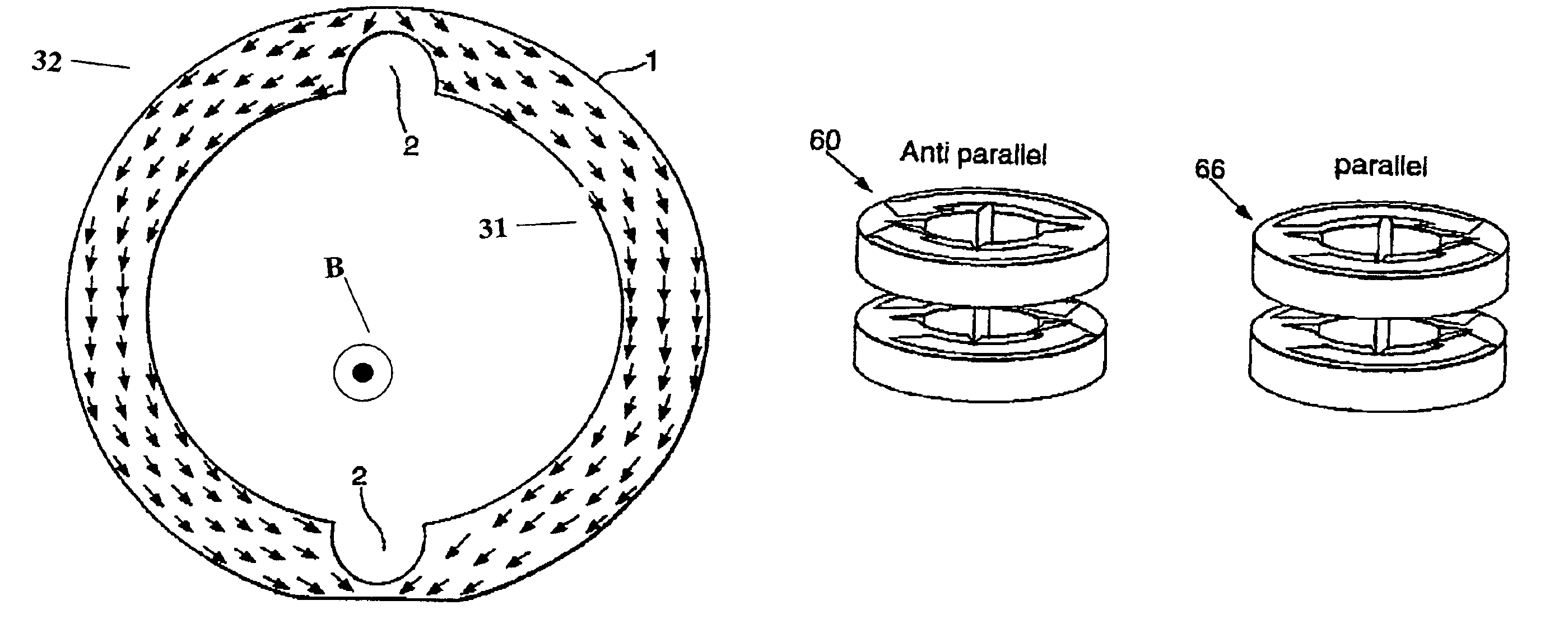
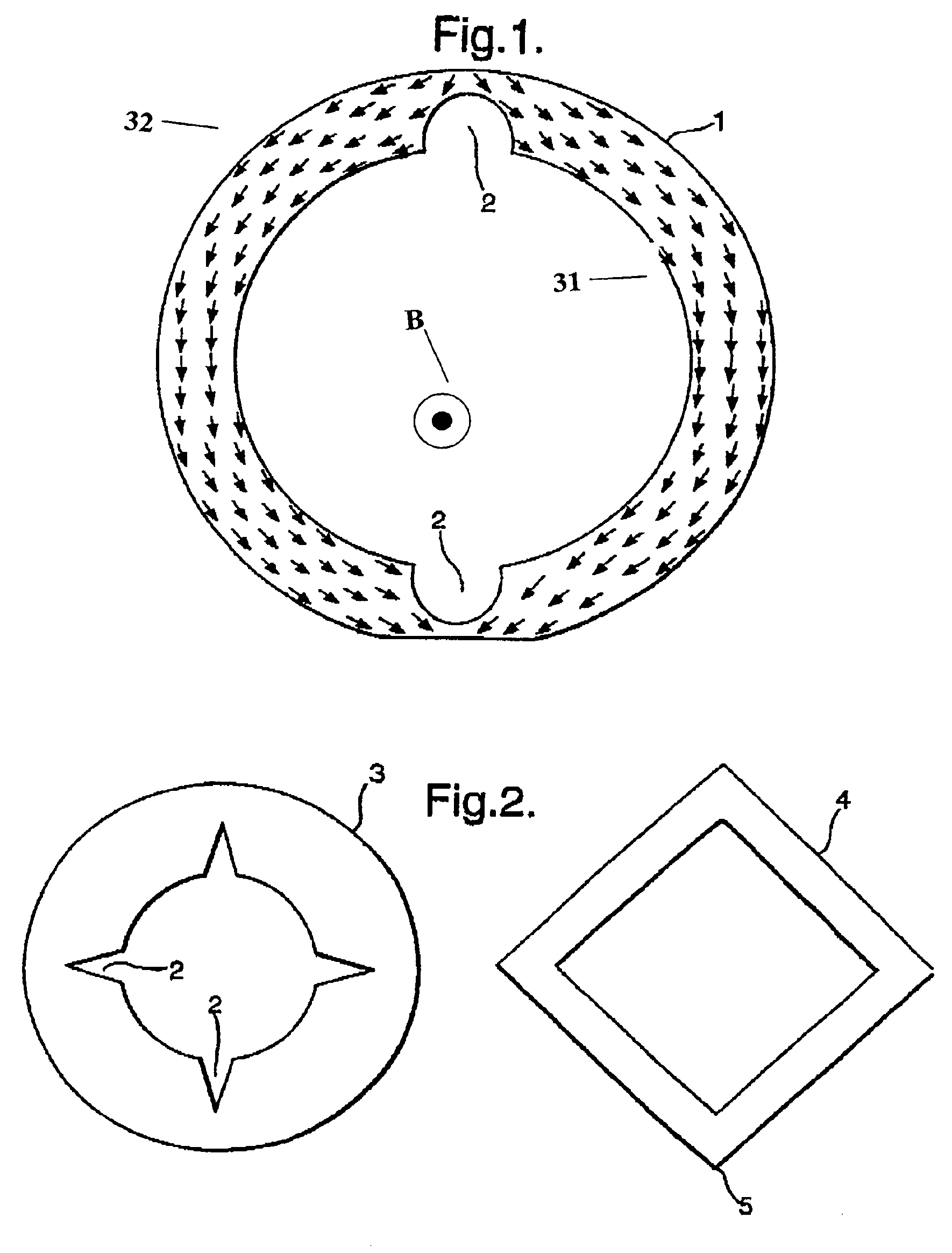
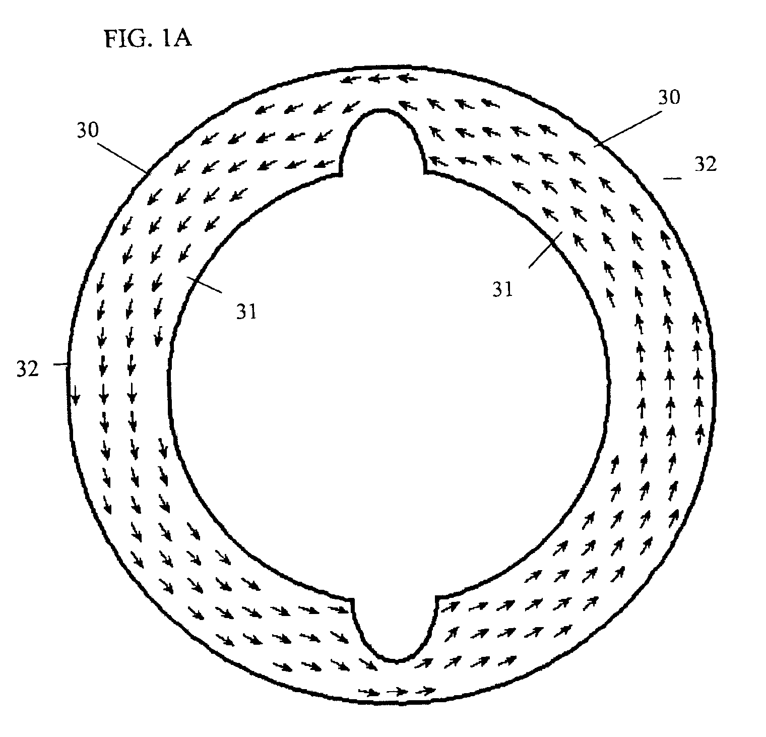
[0023]FIG. 1 shows a ferromagnetic loop 1 according to a first example of the present invention. The loop 1 is substantially circular and has two diametrically opposed notches 2 cut into the inside face of the loop. The diameter of the loop can be the order of a few nanometres. The direction of the magnetic field lines are in the same direction shown by the arrows. In FIG. 1A, the arrows are in opposite directions. The loop as shown comprises two equally sized magnetic domains 30A, 30B separated by two domain walls. The domain walls are located between and include leading edges 31 and trailing edges 32, the narrow portions of the loop by the notches 2. This domain configuration, hereinafter referred to as an “Onion State”, is stable as it is energetically favorable for the loop as a whole. The two dominant energy considerations which determine the stable domain configurations of the loop are the energy associated with the formation of a magnetic domain wall and the energy contained ...


PUM

PropertyMeasurementUnit
thicknessaaaaaaaaaa
magnetisationaaaaaaaaaa
resistanceaaaaaaaaaa

Abstract

A magnetic element comprises a closed loop of ferromagnetic material having an even number of magnetic domains of opposite sense. The magnetisation within the domains is in a circumferential direction, and the domains have leading and trailing walls extending from the inside to the outside of the loop. The magnetic element has a geometry such that there are at least two stable equilibrium domain configurations in which the domain walls are confined in predetermined portions of the loop and wherein the element is switchable between the stable configurations upon the application of a external magnetic field.

Description

BACKGROUND OF THE INVENTION[0001]The present invention relates to magnetic elements with stable but switchable domain structures. These elements are useful in array Magnetic Random Access Memories (MRAM) and in hard disk read / write heads.[0002]The use of magnetic structures in magnetic data storage has intensified during the last 10 years. The main application is found in the read head in hard disk drives, which are based on Anisotropic Magneto Resistive (AMR) thin films and on more complex systems utilising Giant Magneto Resistive (GMR), or Tunnel Magneto Resistive (TMR), multilayers. Another newer application is the use of small magnetic elements to store the data in Random Access Memories. The main qualities needed for these applications, apart from a high magneto resistance, are well defined and reproducible magnetic states having a predictable response to an applied magnetic field. In addition, with the increase in speed in microelectronics, the required switching speed between...

Claims


Application Information

Patent Timeline
Patent Type & Authority Patents(United States)
IPC IPC(8): H01F7/02G11B5/31G11B5/49H01F1/00
CPCB82Y25/00G11B5/31H01F1/0036G11B5/4946G11C19/0808G11C21/00
Inventor BLAND, JAMES ANTHONY CHARLESROTHMAN, BENGT JOHANDIAZ, LUIS LOPEZKLAUI, MATHIAS
Owner CAMBRIDGE ENTERPRISE LTD
Why Eureka
Try Eureka