Scanner having scan angle multiplier

a scanning angle and multiplier technology, applied in the field of optical scanning apparatuses, can solve the problems of changing the wavelength of light beams, complex transmission optical system, and large number of optical components

Inactive Publication Date: 2006-09-05
SEIKO EPSON CORP
View PDF6 Cites 7 Cited by
  • Summary
  • Abstract
  • Description
  • Claims
  • Application Information

AI Technical Summary

Benefits of technology

[0016]A principal object of the present invention is to provide a compact optical scanning apparatus having a simple structure which achieves stable scanning with a light beam and provide an image forming apparatus which comprises such an optical scanning apparatus.
[0017]According to a first aspect of the present invention, a transmission optical system in an optical scanning apparatus comprises a concave surface mirror and a transmission lens, the concave surface mirror being disposed such that a reflection surface of the concave surface mirror is directed toward a deflecting element, the transmission lens being disposed between the concave surface mirror and the deflecting element. A light beam deflected by the deflecting element is guided to the concave surface mirror via the transmission lens while the light beam returned by the concave surface mirror is guided to the deflecting element via the transmission lens, thereby ensuring that the deflection angle of the light beam emitted toward a surface-to-be-scanned after deflected by the deflecting element once again becomes larger than the deflection angle of the light beam impinging upon the transmission optical system.
[0019]According to a third aspect of the present invention, a deflecting element in an optical scanning apparatus deflects a light beam from a light source while a transmission optical system guides thus deflected light beam to the deflecting element, whereby the light beam is emitted to an imaging element after deflected by the deflecting element once again. The transmission optical system exhibits such an imaging characteristic which corrects curvature of field created by the imaging element.
[0020]According to a fourth aspect of the present invention, the imaging element in an optical scanning apparatus condenses a light beam from a light source, the condensed light beam impinges upon a deflecting element and is deflected, a transmission optical system guides thus deflected light beam to the deflecting element, the deflecting element deflects the light beam again, and the light beam is emitted toward a surface-to-be-scanned. The transmission optical system exhibits such an imaging characteristic which corrects curvature of field created by the imaging element.

Problems solved by technology

Since the plurality of transmission lenses are used in this manner, the transmission optical system is complex and contains a great number of optical components.
Further, use of the plurality of transmission lenses also gives rise to another problem: The wavelength of the light beam changes as an environment surrounding the apparatus, in particular an ambient temperature, changes and the apparatus comprising the plurality of transmission lenses is largely influenced by chromatic aberration of the lenses.
This may sometimes make the scan characteristic of the light beam instable, and deteriorate the quality of an image formed on a surface-to-be-scanned.
For this reason, it is not possible to eliminate the influence of aberration such as spherical aberration.
Due to the influence of aberration, it is not possible to obtain a desired trace of the light beam at a location away from the optical axis of the transmission optical system, which is one of main factors which deteriorate the scannability.
This leads to a problem that it is not possible to irradiate the surface-to-be-scanned with a light beam whose spot size is proper.

Method used


Image

  • Scanner having scan angle multiplier
  • Scanner having scan angle multiplier
  • Scanner having scan angle multiplier

Examples


first embodiment

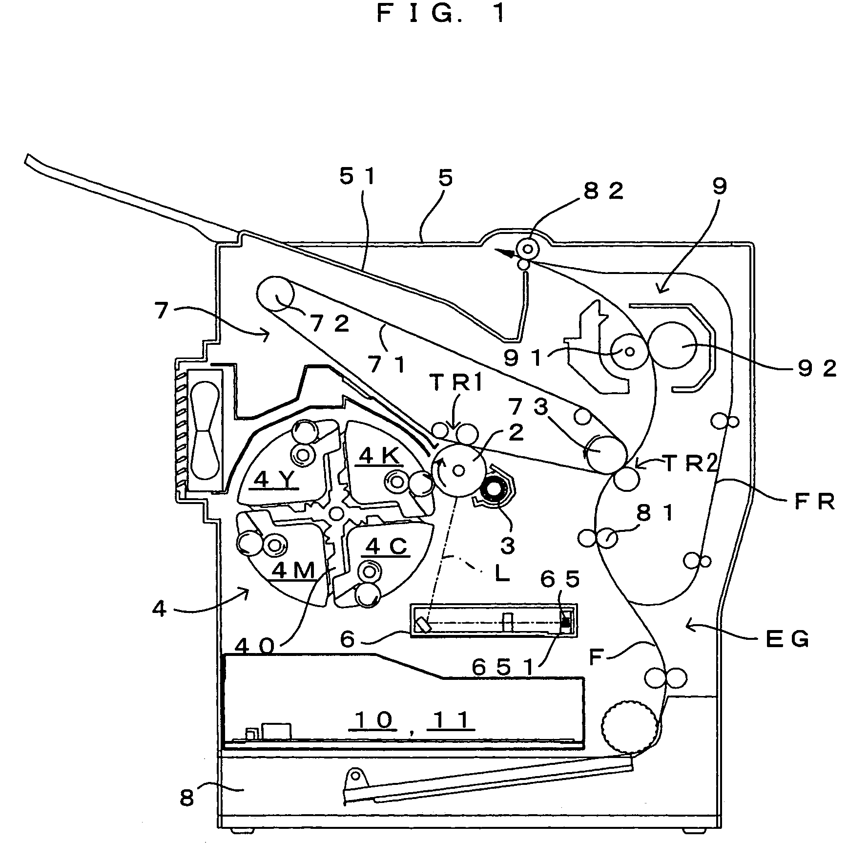
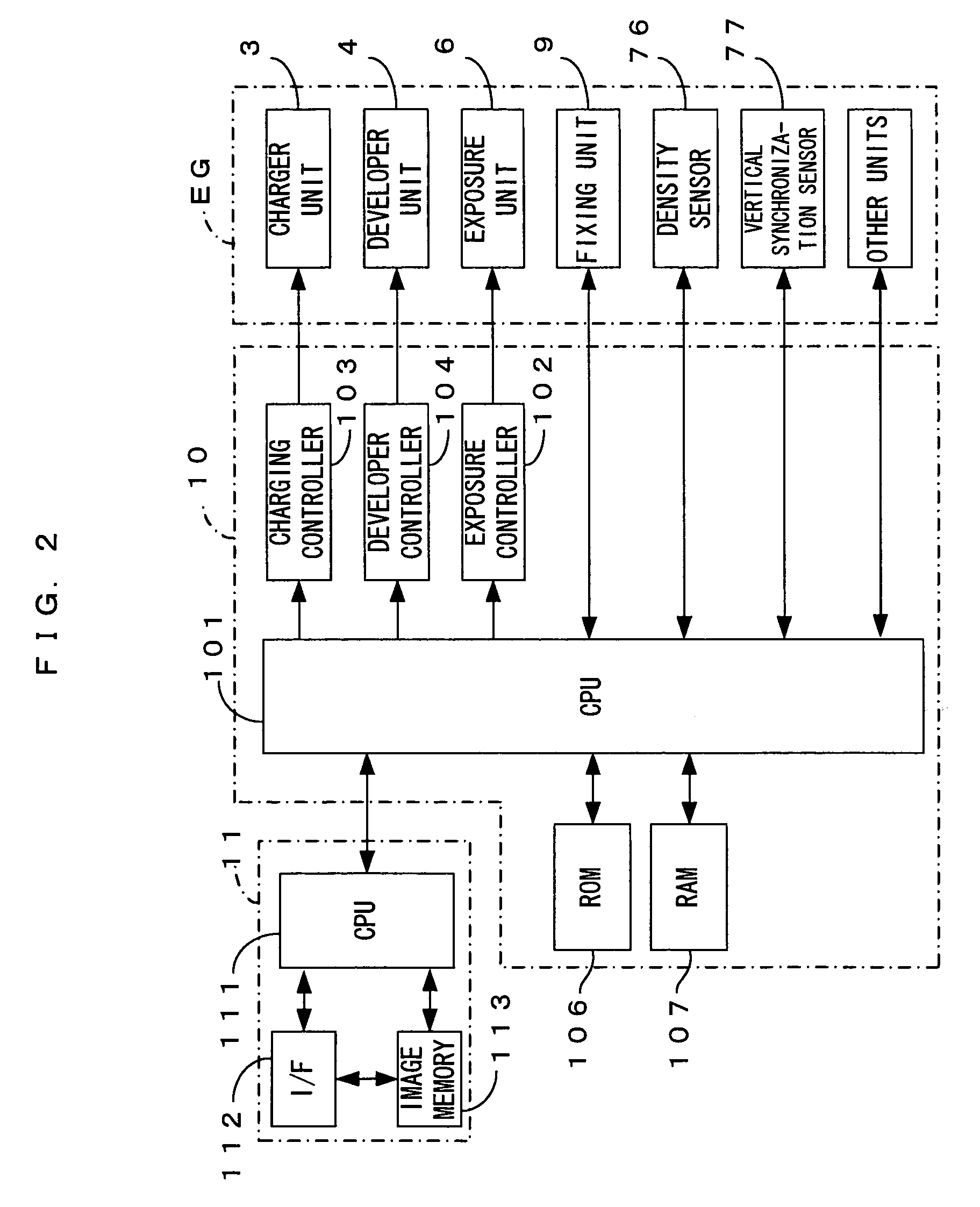
[0041]FIG. 1 is a drawing of an image forming apparatus equipped with an exposure unit which is an optical scanning apparatus according to the present invention. FIG. 2 is a block diagram showing the electric structure of the image forming apparatus which is shown in FIG. 1. This image forming apparatus is a color printer of the so-called 4-cycle method. In this image forming apparatus, when a print command is fed to a main controller 11 from an external apparatus such as a host computer in response to an image formation request from a user, an engine controller 10 controls respective portions of an engine part EG in accordance with the print command from a CPU 111 of the main controller 11, and an image which corresponds to the print command is formed on a sheet which may be a copy paper, a transfer paper, a plain paper or a transparency for an overhead projector.

[0042]In the engine part EG, a photosensitive member 2 is disposed so that the photosensitive member 2 can freely rotate...

second embodiment

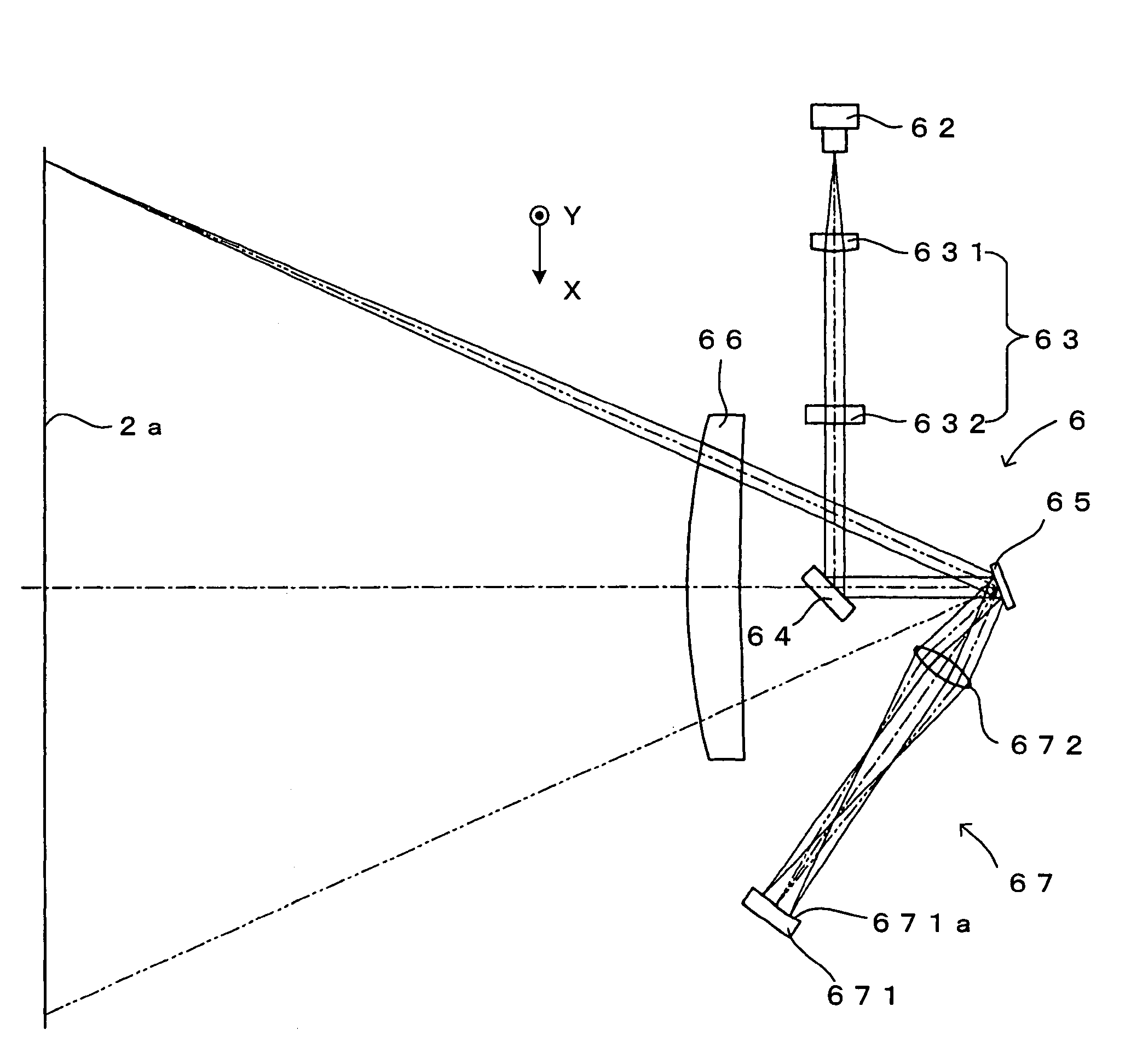
[0091]Further, in the second embodiment, the parallel light beam impinges upon the deflecting element 65 within a main-scanning cross sectional surface and is deflected by the deflecting element 65 at various angles, and the transmission optical system 67 returns thus deflected light beam as a parallel light beam to the deflection mirror surface 651 of the deflecting element 65. Hence, at any deflection angle, the parallel light beam is emitted from the deflecting element 65 toward the surface (surface-to-be-scanned) of the photosensitive member 2. The scanning lens 66 images this parallel light beam upon the surface of the photosensitive member 2 and make the parallel light beam scan in a desired spot diameter.

[0092]In addition, the second embodiment requires that the two transmission lenses 674 and 675 are formed by aspheric lenses having the same structure and are symmetrized with respect to the intermediate image position P3, which permits designing the lenses relatively simple ...


PUM


Abstract

A transmission optical system comprises a concave surface mirror whose reflection surface is directed toward a deflection mirror surface and a transmission lens which is disposed between the concave surface mirror and the deflection mirror surface. A light beam deflected by a deflecting element at a first deflection angle is guided to the concave surface mirror via the transmission lens, and the light beam returned by the concave surface mirror is guided to the deflecting element via the transmission lens. In consequence, the deflecting element reflects the light beam twice, and the light beam is emitted toward a scanning lens at a second deflection angle which is larger than the first deflection angle.

Description

CROSS REFERENCE TO RELATED APPLICATION[0001]The disclosure of Japanese Patent Applications enumerated below including specification, drawings and claims is incorporated herein by reference in its entirely:[0002]No.2003-290710 filed Aug. 8, 2003;[0003]No.2003-324197 filed Sep. 17, 2003; and[0004]No.2003-329275 filed Sep. 22, 2003.BACKGROUND OF THE INVENTION[0005]1. Field of the Invention[0006]The present invention relates to an optical scanning apparatus in which a light beam from a light source is deflected and scans, and in particular, to an optical scanning apparatus in which a light beam impinges upon a deflecting element a plurality of times and a deflection angle accordingly increases, and also to an image forming apparatus which comprises such an optical scanning apparatus.[0007]2. Description of the Related Art[0008]In an attempt to increase a deflection angle, a conventional optical scanning apparatus for use within an image forming apparatus such as a laser beam printer, a ...

Claims


Application Information

Patent Timeline
Patent Type & Authority Patents(United States)
IPC IPC(8): G02B26/08G02B26/10
CPCG02B26/10
Inventor NOMURA, YUJIROIKUMA, KEN
Owner SEIKO EPSON CORP
Why Eureka
Try Eureka