Anti-vibration arrangement

Active Publication Date: 2006-09-12
POSITEC POWER TOOLS (SUZHOU) CO LTD
View PDF11 Cites 37 Cited by
  • Summary
  • Abstract
  • Description
  • Claims
  • Application Information

AI Technical Summary

Benefits of technology

[0063]at least one brake for reducing the rotational speed of at least one of the first and second pads at least when no load is applied to at least o

Problems solved by technology

However, these limitations reduce the efficiency of the machine.
In order to compensate for these limitations in efficiency, operators frequently apply a certain pressure or load to the tool in order to increase the friction on the work piece with the result that vibrations are amplified.
By doing this, the effective mass of the machine is increased and the vibrations are absorbed by the operator's hand and arm with often severe consequences for the operator's health.
For example, even low usage operators may experience numbness and tingling in their fingers, hand and arm within a few minutes of operation and this may be lead to an unpleasant loss of feeling and control in the fingers that can last for hours after use has ceased.
If use is prolonged for hours, a full recovery can take several days.
The conseque

Method used


Image

  • Anti-vibration arrangement
  • Anti-vibration arrangement
  • Anti-vibration arrangement

Examples


first embodiment

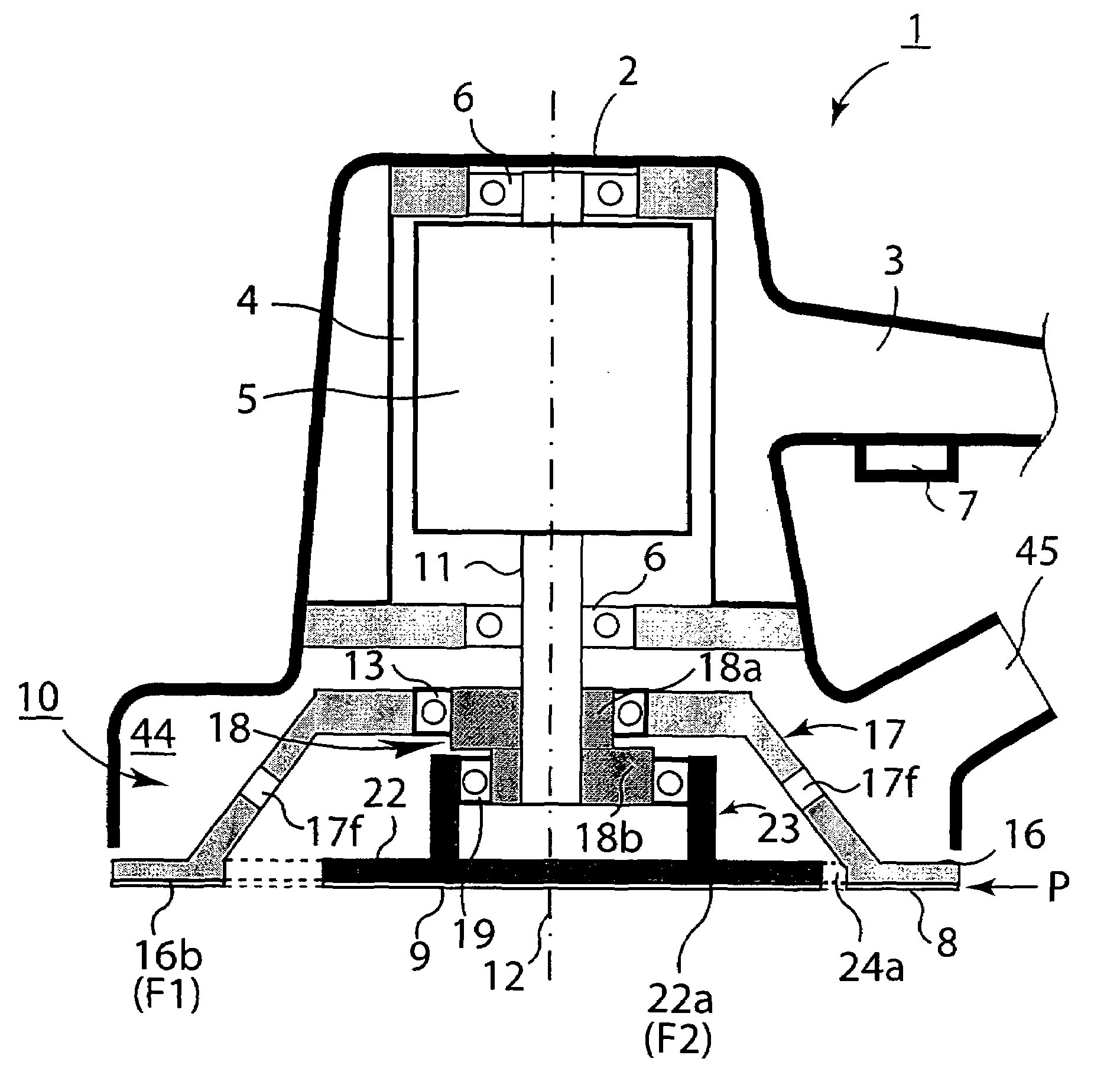
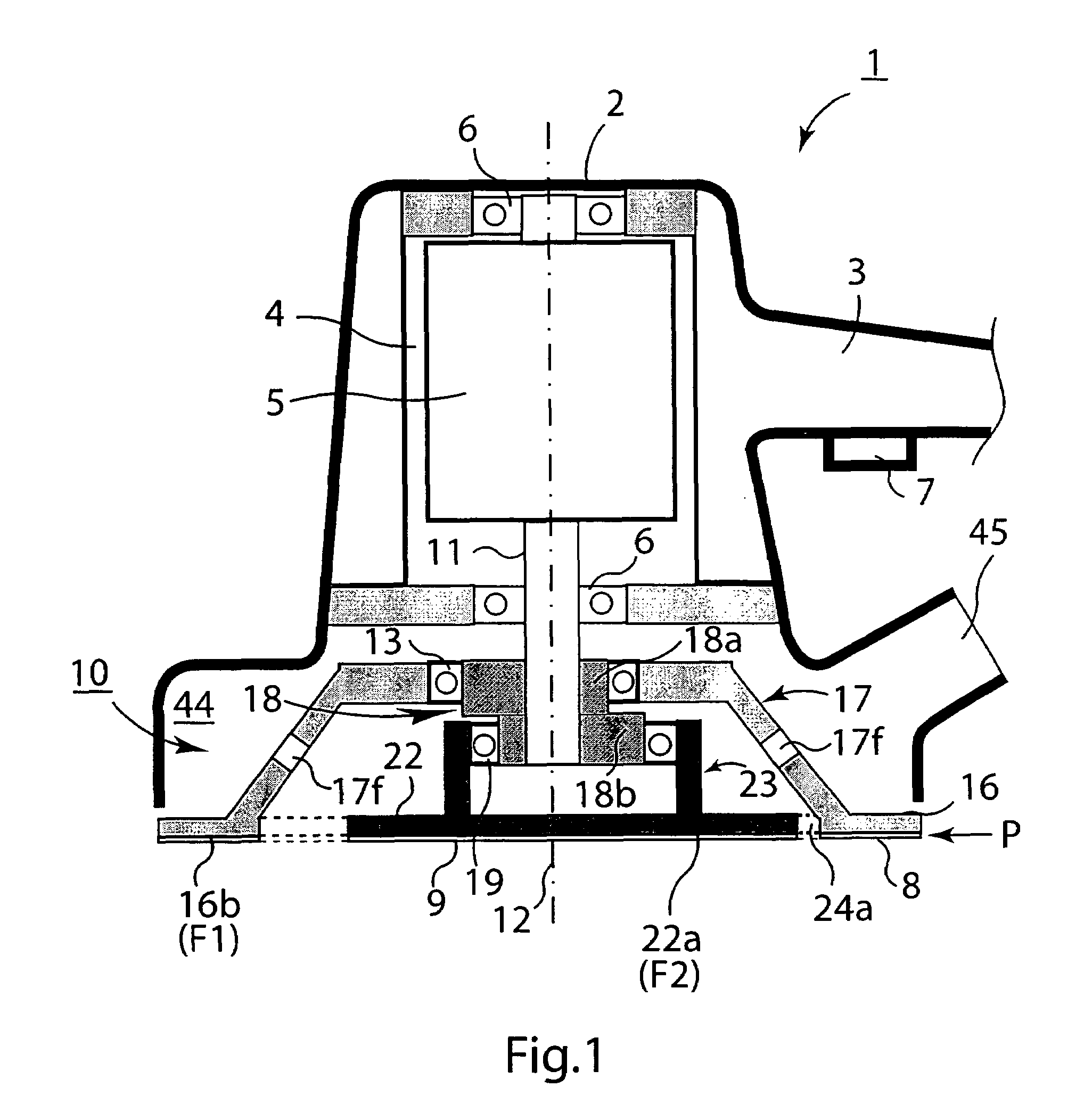
[0079]FIG. 1 illustrates a rotary sander 1 incorporating an anti-vibration arrangement 10 according to the present invention. The rotary sander 1 generally includes a housing 2 that has a handle or grip 3 and an internal volume 4 for housing an electric motor 5 with a variable speed of 2000 to 12000 rpm. The housing 2 is provided with an exhaust tube 45 beneath the handle 3 for exhausting air and dust from the interior 44. The electric motor 5 has a rotary drive shaft 11 with a longitudinal rotary axis 12 which is supported at the upper end of the housing 2 by ball, cylinder or oil bearings 6. A power switch 7 is positioned on the handle 3 and the rotary sander 1 is connected to mains power, a rechargeable battery or a compressed air tank which is not represented in FIG. 1. The anti-vibration arrangement 10 couples the rotary drive shaft 11 to abrasive elements (such as abrasive layers or sanding papers) for abrading a work piece (not shown) as described below.

[0080]Referring to FIG...

second embodiment

[0098]The second embodiment is driven by a drive shaft assembly and a gear assembly. The drive shaft assembly may be similar to that of FIG. 6 ie including two cams for neighboring pads A1, A3 and A2, A4, wherein each of the two drive shaft assemblies is connected to the rotary drive shaft 11. By such drive shaft assemblies and the gear assembly, the rotation of the rotary axis 12 is transferred to the four axes S1, S2, S3, S4 so that the external pad surfaces B1–B4 rotate in the directions T1–T4. The circles C1–C4 shown in solid line indicate the location of the associated cylindrical cam in the first position (1) whereas the circles shown in broken lines indicate the location of the associated cylindrical cam in the third position (3). In this embodiment, a significant reduction of vibrations is obtained. In addition to orbiting, the entire configururation will rotate arround the rotary axis 12, thereby performing pad rotations for coarse sanding.

[0099]FIG. 15 is a partial side vi...


PUM


Abstract

The present invention relates to an anti-vibration arrangement (10) for a power sander (1) which comprises a housing (2), a motor (4) arranged in the housing (2), a rotary drive shaft (11), a first outer or ring-shaped pad surface (16) for attaching a first sanding paper (8) and a second inner or circular pad surface (22) for attaching a second sanding paper (9). The anti-vibration arrangement (10) serves to transfer energy from the motor (4) to the pads (16, 22) with out-of-phase motions to dynamically compensate for inertial and friction forces. For this purpose, twin cams (18a, 18b) are fixed on the rotary drive shaft (11). The cams (18a, 18b) rotate the central axes (15, 21) of the pads (16, 22) about the rotary drive shaft axis (12) with a phase differential of typically 180°. Vibration which would otherwise be transmitted to the rotary drive shaft (11) and from there to the operator of the machine (1) are drastically reduced irrespective of whether or not the operator increases the applied force (1) in order to increase the sanding depth or to speed up the sanding operation.

Description

REFERENCES TO RELATED APPLICATIONS[0001]This is a non-provisional application claiming priority to European Application Number 05252417.0, entitled Anti-Vibration Device, filed 18 Apr. 2005, which is hereby incorporated by reference in its entirety.FIELD OF THE INVENTION[0002]The present invention relates to an anti-vibration arrangement for an eccentrically rotary and oscillatory tool (eg an abrasive power tool) such as an orbital sander or polisher, to a power tool incorporating the anti-vibration arrangement and to a method for abrading a work piece.BACKGROUND OF THE INVENTION[0003]Orbital power tools such as sanders and polishers generally include a pad that is normally adapted to support an abrasive element such as sanding paper. The pad is coupled by a transmission means to a motor arranged in a housing. The transmission means can incorporate a cam rotationally driven by the rotary drive shaft. The cam is housed in a circular aperture that is positioned in the centre of the pa...

Claims


Application Information

Patent Timeline
IPC IPC(8): B24B7/00
CPCB24B23/03B24B27/0076B24B23/04
Inventor BORINATO, GIANNIANDRIOLO, PAOLO
Owner POSITEC POWER TOOLS (SUZHOU) CO LTD
Why Eureka
Try Eureka