Apparatus for forming a microfiber coating

a technology of microfibers and coatings, applied in the direction of spraying apparatus, coatings, bandages, etc., can solve the problems of not providing a consistent quality of microfibers and a sterile dressing, and achieve the effect of reducing moisture and enhancing removal of moistur

Inactive Publication Date: 2006-09-12
POLYREMEDY
View PDF6 Cites 42 Cited by
  • Summary
  • Abstract
  • Description
  • Claims
  • Application Information

AI Technical Summary

Benefits of technology

[0006]The present invention, according to one embodiment, is a method for forming a fiber coating on a surface, from a supply of fiber-forming liquid having moisture, in an environment having an ambient pressure. The method includes the steps of applying an electrical potential between the supply an

Problems solved by technology

The techniques known in the art, however, have several shortcomings, including

Method used


Image

  • Apparatus for forming a microfiber coating
  • Apparatus for forming a microfiber coating
  • Apparatus for forming a microfiber coating

Examples


example

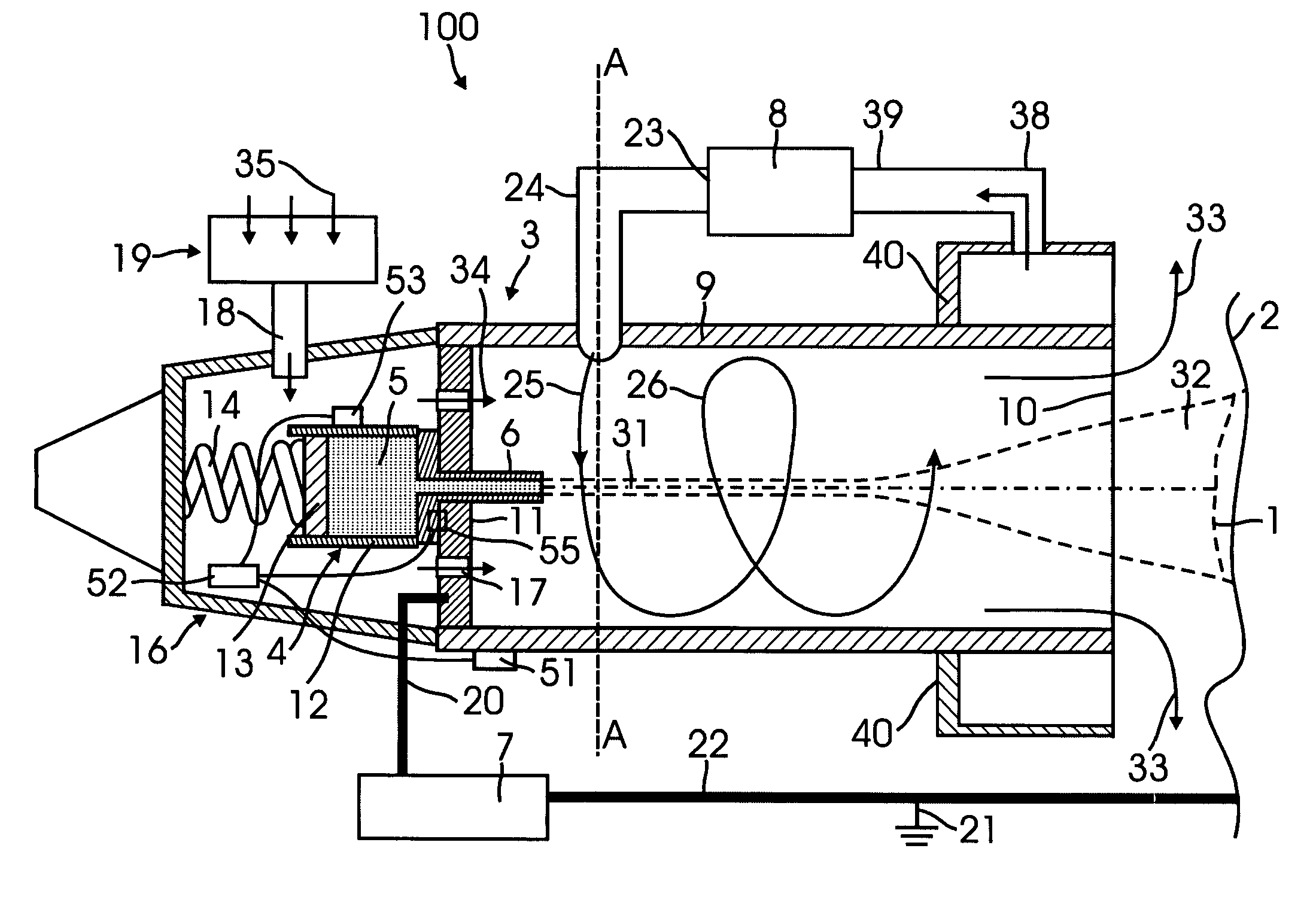
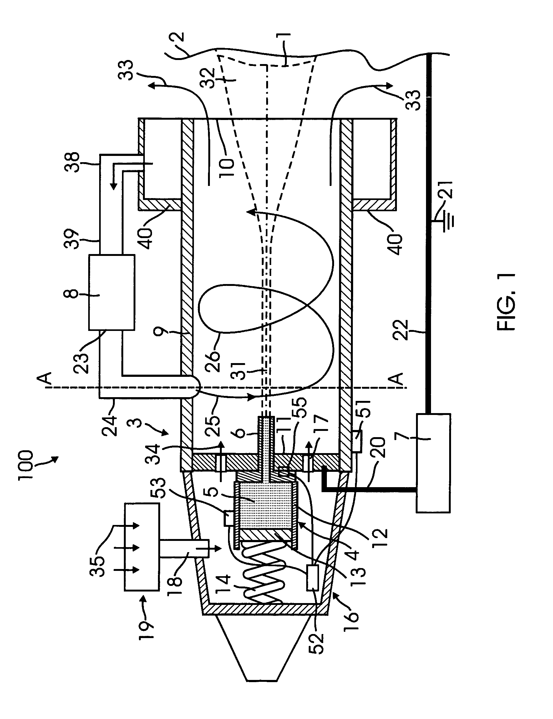
[0062]The device shown in FIG. 7 was for application of a microfiber coating 1 on human skin. The mixture 5 included polyvinilpirralidone (M=360,000) and poly-d,l-lactide (M=150,000), in ratio 1:10, and 80% of solvent ethyl acetate. The flow rate of the mixture 5 was 1 mL / min, the flow rate of the compressor 8 was 30 l / min, the flow rate of the additional air flow with controlled relative humidity of about 10% was 6 l / min. The electrical field strength between the capillary 6 and the surface 2 was 1.5 kV / cm. The distance between the outlet 10 and the surface 2 was 1 cm. The size of the microfibers was about 0.2 microns. The thickness of the microfiber coating 1 was 1 mm. Emission of solvent vapors was insignificant.

[0063]A method and device embodying the invention may also be used for non-medical or skin treatment purposes. For example, coatings of fibers, particles or microcapsules may be formed on substrates such as paper with good control of the thickness and uniformity of the co...


PUM

PropertyMeasurementUnit
Pressureaaaaaaaaaa
Electrical conductivityaaaaaaaaaa
Flow rateaaaaaaaaaa

Abstract

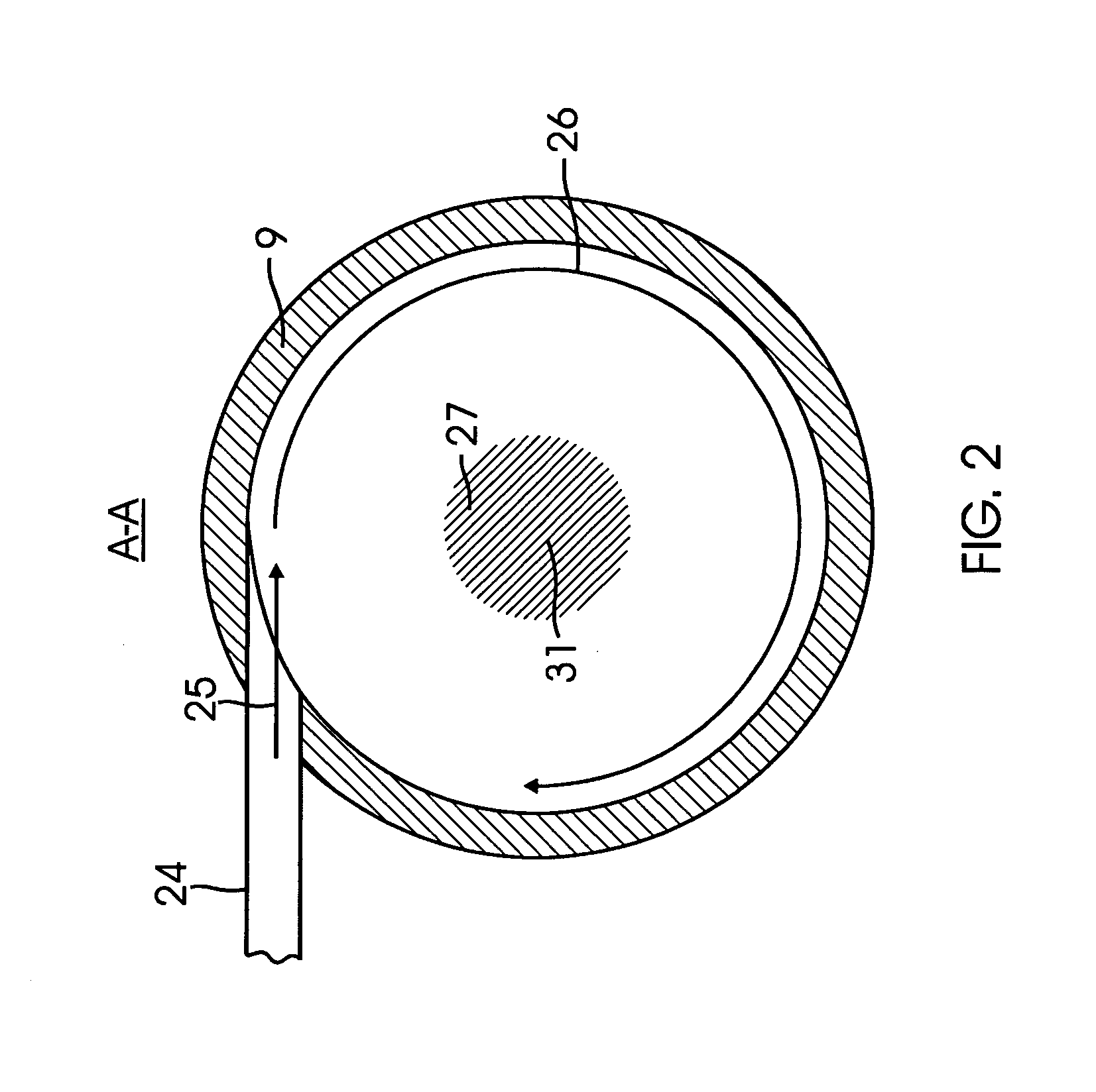
An apparatus and method for forming a microfiber coating includes directing a liquid solution toward a deposition surface. The apparatus includes a tube defining a volume through which the liquid solution travels. An electric field is applied between the origin of the liquid solution and the surface. A gas is injected into the tube to create a vortex flow within the tube. This vortex flow protects the deposition surface from entrainment of ambient air from the surrounding atmosphere.

Description

CROSS-REFERENCE TO RELATED APPLICATION[0001]This application claims priority to U.S. provisional patent application No. 60 / 362,175 filed Mar. 5, 2002, the entire content of which is incorporated herein by this reference.SCOPE OF THE INVENTION[0002]The present invention relates to electro-hydrodynamic fiber forming, also commonly referred to as electro or electrostatic spinning. More specifically, it relates to using electro-hydrodynamic fiber forming to provide a mat of woven fibers.BACKGROUND[0003]Electro-hydrodynamic fiber forming generally involves the introduction of a liquid into an electrical field. The resulting electrical forces create a jet of liquid which carries an electrical charge. These liquid jets may be attracted to other electrically-charged objects at a suitable electric potential. As the jet of liquid travels, it elongates and it will harden and dry. The hardening and drying of the elongated jet of liquid may be caused by cooling of the liquid (e.g., where the liq...

Claims


Application Information

Patent Timeline
IPC IPC(8): B05C11/10A61F15/00B05B1/28
CPCB05B5/03B05B5/1675B05B5/1691D04H11/00D04H1/70D04H3/02D01D5/0084D04H1/76B05B5/006B05B7/10B05B12/004B05B12/081B05B12/124B05B5/032
Inventor SINYAGIN, DMITRIY
Owner POLYREMEDY
Why Eureka
Try Eureka