Thermoplastic multi-layer composite structure

a composite structure and multi-layer technology, applied in the field of thermoplastic composite materials, can solve the problems of low energy absorption, low production efficiency, and low efficiency of fiberglass primary components, and achieve the effect of less maintenan

Inactive Publication Date: 2006-09-12
BRUNSWICK CORPORATION
View PDF7 Cites 7 Cited by
  • Summary
  • Abstract
  • Description
  • Claims
  • Application Information

AI Technical Summary

Benefits of technology

[0022]Polypropylene is a member of a family of plastics called olefins and is a crystalline structure. The high density polypropylene provides for a relatively hard and stiff surface. The polypropylene also provides for a high degree of recyclability.
[0032]It is a further object of the present invention to provide a thermoplastic multi-layer composite structure which does not contain toxic materials.

Problems solved by technology

As seen from the above description, the manufacture of products using fiberglass as a primary component is relatively expensive and labor intensive.
Furthermore, fiberglass does not have good energy absorbing characteristics, which causes nearly all of the impact forces to be translated through the fiberglass.
In view of the translation of all of the wave energy, in certain conditions the passengers and driver on the boat may experience an unpleasant boat ride.
However, under pressure the injected foam expands.
As seen from the above description the forming processes required when utilizing polyurethane or urethanes are relatively involved and costly.
Furthermore, the end product constructed from polyurethane have several drawbacks as they are normally less durable and are normally not recyclable.
Furthermore, polyurethanes are known to contain a great deal of toxicity.

Method used


Image

  • Thermoplastic multi-layer composite structure
  • Thermoplastic multi-layer composite structure
  • Thermoplastic multi-layer composite structure

Examples


Embodiment Construction

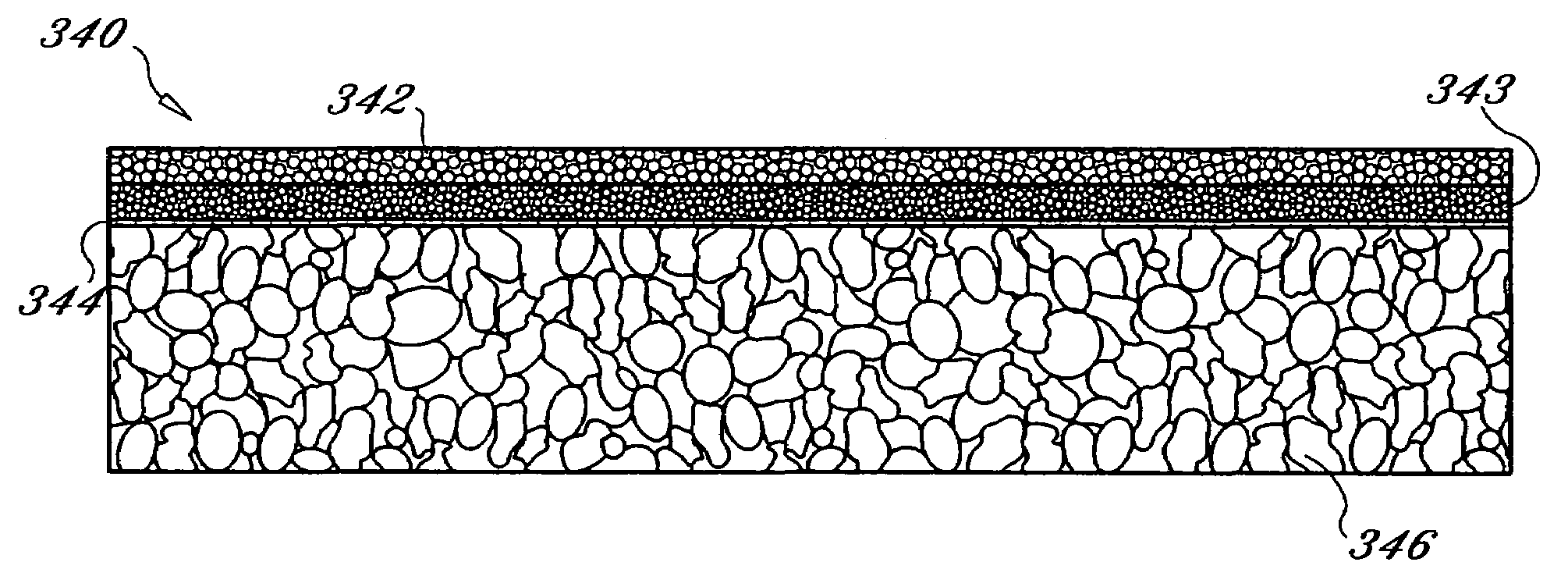
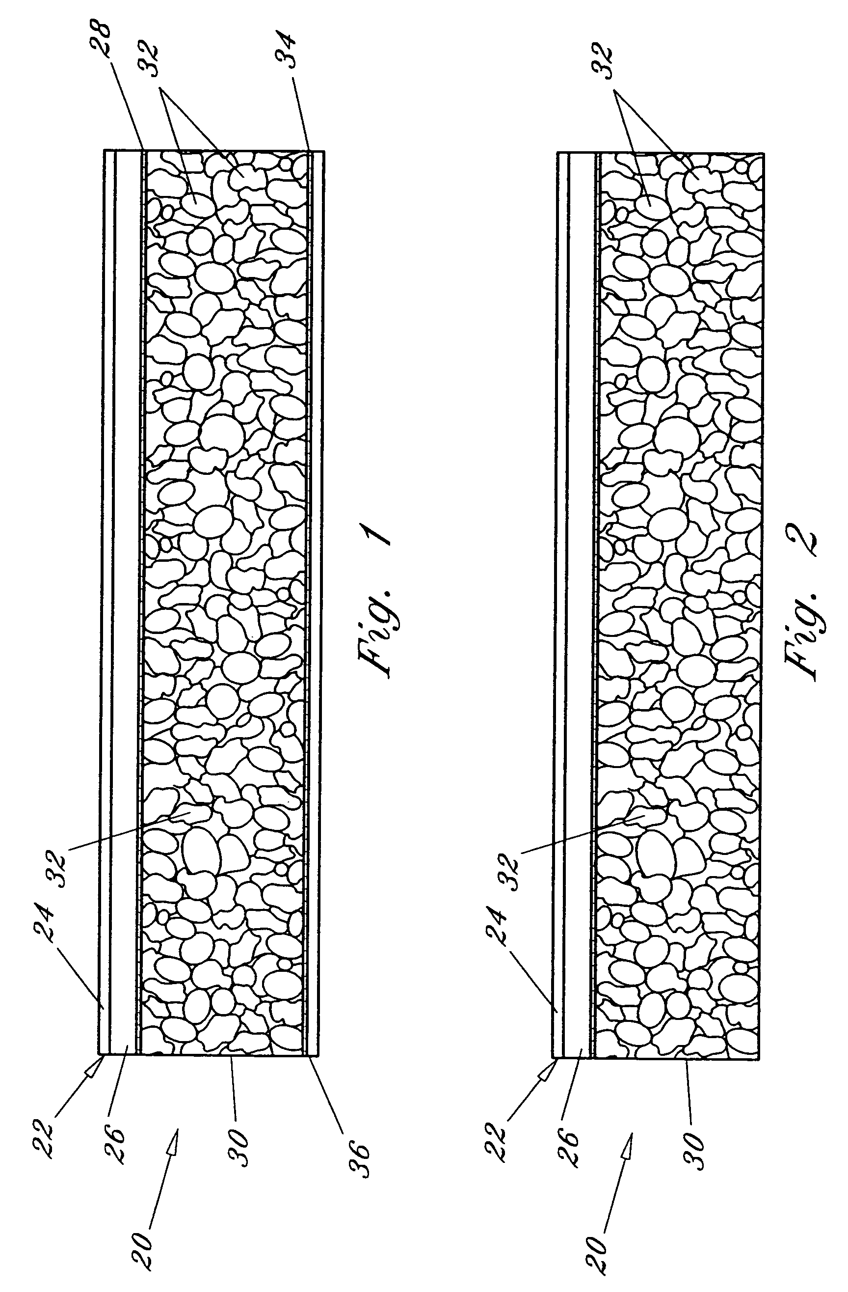
[0054]FIGS. 1 and 2 illustrate a first embodiment of a thermoplastic multi-layered composite structure in accordance with the present invention with the composite structure being generally designated as reference numeral 20. Composite structure 20 generally includes a top skin 22 and a foam core 30. Where necessary for extra strength purposes an inner or back skin 36 can also be provided to help reduce fracturing of foam core 30. Back skin 36 can be vacuumformed during construction, however, such is not limiting.

[0055]In the preferred embodiment top skin 22 consist of an acrylic polypropylene outer layer 24 and a polypropylene substrate 26. An amorphous material can also be added to the acrylic polypropylene outer layer 24 to increase the impact strength of top skin 22. Preferably, substrate 26 has a high melt strength. Top skin 22, consisting of a weatherable acrylic polypropylene outer layer 24 and high melt strength substrate 26, can also be referred to as a cap sheet. Outer laye...


PUM

PropertyMeasurementUnit
temperatureaaaaaaaaaa
structureaaaaaaaaaa
thickaaaaaaaaaa

Abstract

A thermoplastic multi-layer composite structure is disclosed and consist in a first embodiment of a co-extruded acrylic polypropylene outer skin and high melt strength polypropylene substrate which is attached to a first surface of a polypropylene foam core. An inner polypropylene skin can be provided and is attached to a second surface of the foam core. The foam core can either be constructed from an expanded polypropylene or an extruded polypropylene. Where an expanded polypropylene foam core is provided, the foam core is attached to the outer and inner skin through the use of a polypropylene adhesive. Where the extruded polypropylene foam core is provided, the skins can be attached to the foam core through a welding or bonding process in lieu of adhesives. The polypropylene adhesives can also be utilized for attaching the skins to the extruded foam core. Additionally, the extruded foam core can vary in density to provide a composite foam core. Preferably, the various densities of the composite foam core are arranged such that the lowest density foam is provided at the center of the core and the varying densities of the foam core extend outward from the center in numerical order. In an alternative embodiment, an all acrylic composite multi-layered structure is provided.

Description

[0001]This application is a divisional application of U.S. patent application Ser. No. 09 / 315,390, filed May 20, 1999, now U.S. Pat. No. 6,878,437 which is a continuation-in part of U.S. patent application Ser. No. 08 / 846,143, filed Apr. 25, 1997, now U.S. Pat. No. 5,916,672.BACKGROUND OF THE INVENTION[0002]1. Field of the Invention[0003]The present invention relates generally to thermoplastic composite materials and more particularly to a thermoplastic multi-layer composite structure.[0004]2. Description of the Prior Art[0005]Thermoplastic composite materials are well known and used in various industries including the marine industry. Recently, with the movement towards improving the environment, several regulations, treaties and laws have been passed to help protect the environment.[0006]Currently, in the marine industry, as well as numerous other industries, the use of fiberglass as a construction material is highly prevalent. Fiberglass is defined as a material consisting of ext...

Claims


Application Information

Patent Timeline
Patent Type & Authority Patents(United States)
IPC IPC(8): B32B38/04B32B5/18
CPCB32B5/18Y10T156/1064Y10T156/1026Y10T156/1067Y10T156/1082Y10T156/1062Y10T428/233B32B7/12B32B27/065B32B27/304B32B27/32B32B37/12B32B37/153B32B2266/025B32B2355/02Y10T428/249981Y10T428/249985Y10T428/249988Y10T428/249991Y10T428/249992Y10T428/249993
Inventor CRANE, STEPHEN
Owner BRUNSWICK CORPORATION
Why Eureka
Try Eureka