Communication device having delay information calculating function

a technology of delay information and communication device, which is applied in the field of communication device having delay information calculating function, can solve problems such as the inability to recognize receiving radio waves, and achieve the effect of improving propagation efficiency

Inactive Publication Date: 2006-09-12
DENSO CORP
View PDF13 Cites 8 Cited by
  • Summary
  • Abstract
  • Description
  • Claims
  • Application Information

AI Technical Summary

Benefits of technology

[0010]The present invention has another object to provide a communication device, which determines delay information of receiving radio waves and improves the propagation efficiency based on thus determined delay information.

Problems solved by technology

The receiver in turn has a problem that it cannot recognize the receiving radio waves delayed far more than the guard interval time correctly as the receiving radio waves.

Method used


Image

  • Communication device having delay information calculating function
  • Communication device having delay information calculating function
  • Communication device having delay information calculating function

Examples


first embodiment

[0029][First Embodiment]

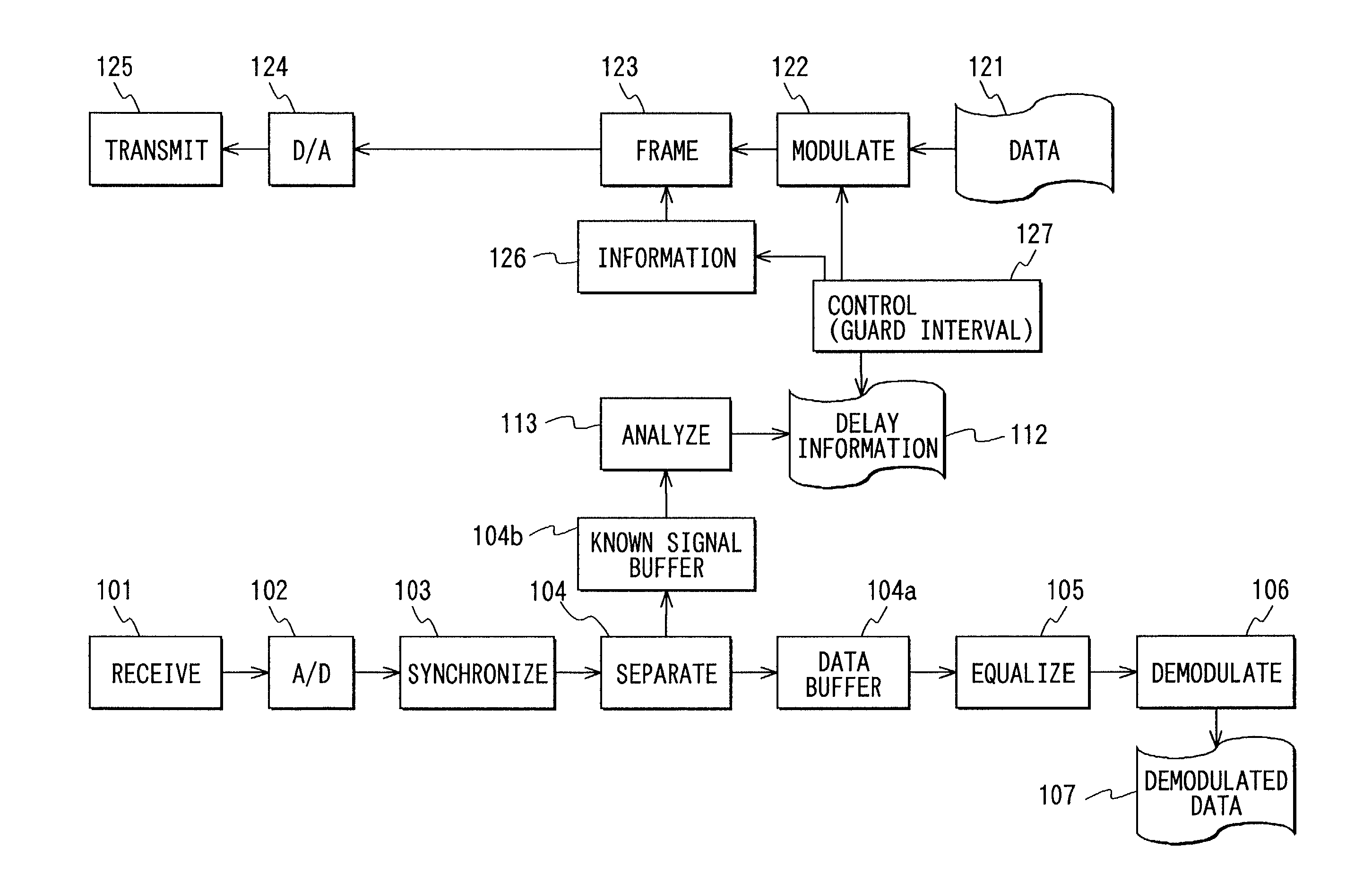
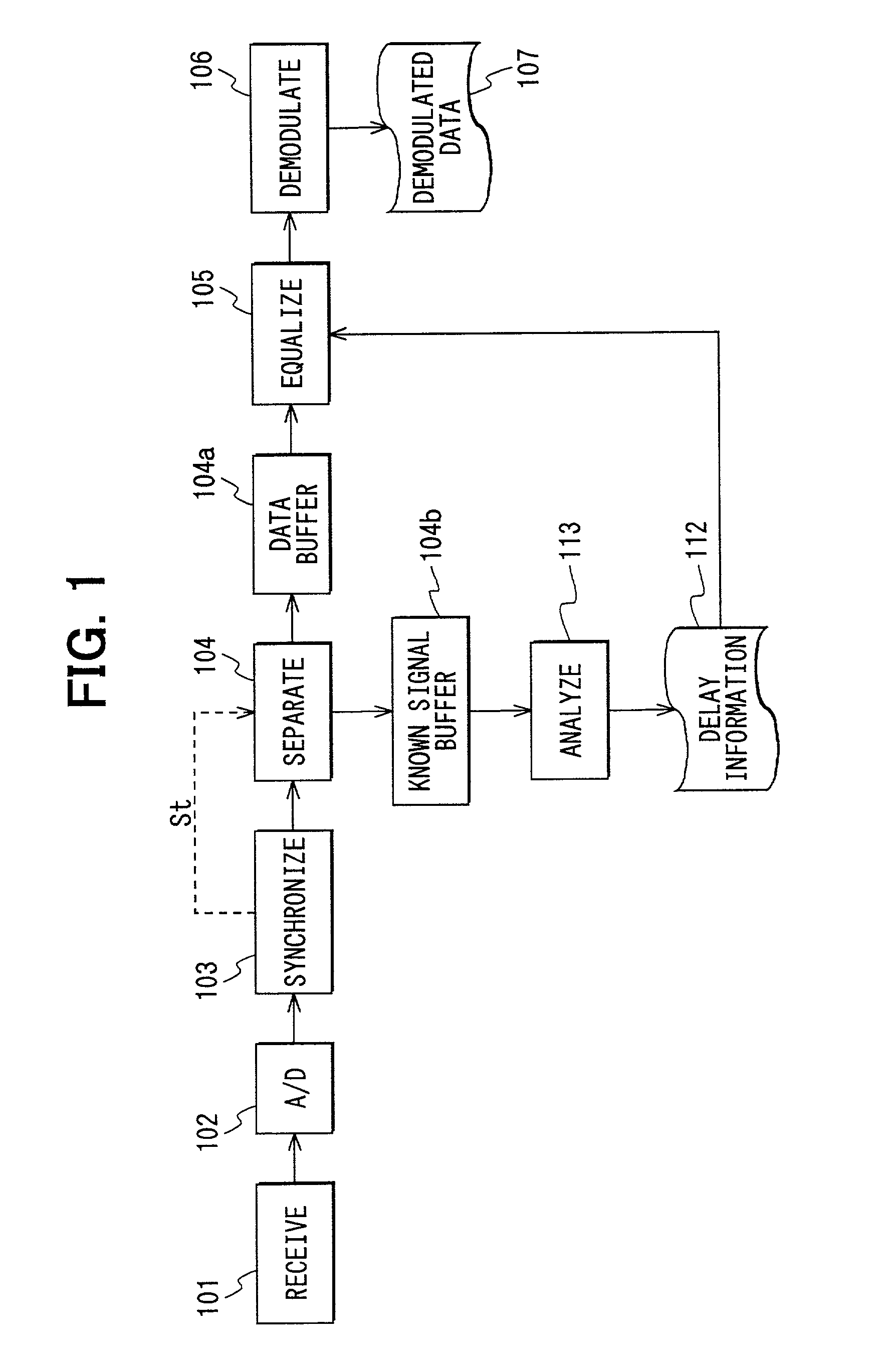
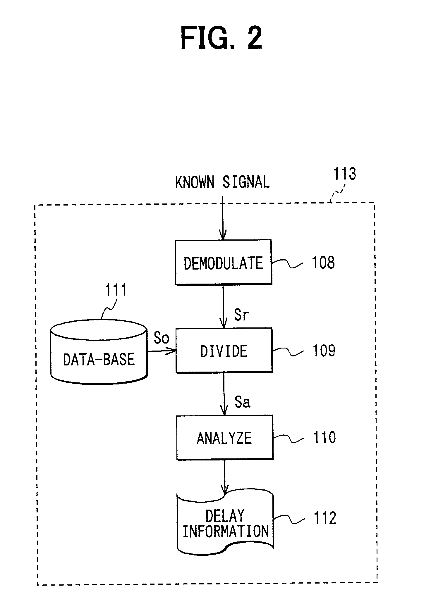
[0030]In FIG. 1 and FIG. 2, there is shown first embodiment of a communication device of the orthogonal multiplexing carrier method in accordance with the present invention. FIG. 1 is a schematic block diagram of circuit in the communication device, while FIG. 2 is a schematic block diagram of circuitry in the delay analyzer circuit shown in FIG. 1.

[0031]The OFDM signals have a number of (N) sub-carriers placed on the frequency axis at a regular interval. The communication device of the orthogonal multiplexing carrier method is referred to as communication device hereinbelow for the sake of simplicity. In the first embodiment, a typical example of usage is assumed for the description of the present invention, wherein the communication device is used in an outdoor wireless communication environment for receiving multiplexed waves. The multiplexed wave includes a plurality of receiving radio waves (delayed waves) arriving at different delayed time from one tran...

second embodiment

[0070][Second Embodiment]

[0071]In the second embodiment, an example is described in which the length (time) of guard interval is optimized by using the computation result of the amount of shift Sa as described in the first embodiment in order to transmit the OFDM signals. In the second embodiment, the data structure of the OFDM signals shown in FIG. 11 is used instead of the data structure shown in FIG. 3.

[0072]In the OFDM signal shown in FIG. 11, a header 13 is added to the data structure shown in FIG. 3. The header 13 is placed between the known signal 10 and the data-1 signal 11. The header 13 has a header guard interval 13a placed at the leader of data sector. Other structure is the same as the data structure shown in FIG. 3. In FIG. 11, data-2 signal 11 is also shown, which signal is omitted in FIG. 3.

[0073]The communication device in accordance with the second embodiment includes, as shown in FIG. 10, a data modulator circuit 122, a synthetic frame generator circuit 123, a dig...

third embodiment

[0091][Third Embodiment]

[0092]In the third embodiment, the arrival direction of each of the receiving radio waves in addition to the delay and receiving power of each of receiving radio waves is determined. FIG. 14 is the overview of this arrangement.

[0093]The communication device shown in FIG. 14 includes a plurality of (M) sets of: an antenna 100, a receiver 101, analog-to-digital converter 102, synchronizer circuit 103, known signal / data separator 104, known signal buffer 104b and divider 109, as well as a database 112, an arrival direction / delay analysis processing circuit 136, and a data demodulator circuit 106. In FIG. 14, the similar or substantially same members are designated with the identical reference numbers to FIG. 1 and FIG. 2. Each of M sets of antennas 100 has the identical characteristics sufficient to constitute an array antenna. Each of M sets of dividers 109 determines fluctuation results SA1, SA2, . . . , SAM, respectively. The database 112 stores the known sig...


PUM


Abstract

A communication device using orthogonal multiplexing carrier method for determining delay information of received radio waves. In this device, a known signal demodulator performs OFDM demodulation to output demodulated signal, and a divider performs a complex division of the demodulated signal with a data sector of known signal of a database for each sub-carrier. By the data section of the known signal, the computation result of the amount of shift can be determined for each of sub-carriers. A delay analytical calculation circuit uses the computation result of the amount of shift for sub-carriers to analyze the delayed waves. For delay analysis, ESPRIT method is used to determine delay information by means of computation result of the amount of shift for each sub-carrier.

Description

CROSS REFERENCE TO RELATED APPLICATION[0001]This application is based on and incorporates herein by reference Japanese Patent Application No. 2000-199440 filed Jun. 30, 2000.BACKGROUND OF THE INVENTION[0002]1. Field of the Invention[0003]The present invention relates to a communication device and more particularly to a communication device using a communication method of simultaneous transmission and reception of a plurality of carriers.[0004]2. Related Art[0005]Recently, multiplexing carrier methods are used for improving the wireless communication speed. In particular, OFDM (orthogonal frequency division multiplexing) method uses a plurality of sub-carriers (carriers) placed on a frequency axis, the interval between adjoining two sub-carriers among the plurality of sub-carriers is implemented as the theoretical minimum. The OFDM method has thereby become one good candidate of orthogonal multiplexing carrier methods that allows the usage rate of frequencies to be improved.[0006]The...

Claims


Application Information

Patent Timeline
Patent Type & Authority Patents(United States)
IPC IPC(8): H04L7/00H04J11/00H04B7/005H04B7/08H04L27/26
CPCH04L27/2647H04B7/086
Inventor MATSUGATANI, KAZUOKITANAKA, MAKOTO
Owner DENSO CORP
Why Eureka
Try Eureka