Apparatus including a radiation source, a filter system for filtering particles out of radiation emitted by the source, and a processing system for processing the radiation, a lithographic apparatus including such an apparatus, and a method of filtering particles out of radiation emitting and propagating from a radiation source

a radiation source and filter system technology, applied in the direction of electrodes and associated parts, radiation therapy, therapy, etc., can solve the problems of reducing affecting the efficiency of radiation transferring, and affecting the effect of radiation transferring efficiency

Inactive Publication Date: 2006-09-12
ASML NETHERLANDS BV
View PDF3 Cites 33 Cited by
  • Summary
  • Abstract
  • Description
  • Claims
  • Application Information

AI Technical Summary

Benefits of technology

[0008]It is an aspect of the present invention to provide an apparatus including a radiation source, a processing system configured to process the radiation from the radiation source and a filter system configured to reduce the number of particles traveling away from the radiation source that reach the processing system, wherein the filter system provides for more freedom of design in positioning the filter system with respect to the radiation source as compared to filter systems known in the prior art.
[0013]In each of the above aspects of the present invention the foils or plates are transported in a substantially translatory movement along at least a part of the trajectory which extends within the beam. Incorporating the translatory movement of the foils allows the design of a multitude of possible trajectories. Hence the design of the trajectory can be chosen such that the design of the filter system can easily be adapted to dimensions and / or arrangements of the radiation source and / or processing system.

Problems solved by technology

Plasma radiation sources, however, besides EUV radiation, often generate debris.
Part of the rotation unit blocks part of the radiation from entering the optical system, e.g. thus reducing the radiation transferring efficiency of the debris removing system Furthermore the attracting unit occupies a large volume close to the radiation source, so that placement of the debris removing system becomes difficult and / or the volume available for the radiation source is limited.

Method used


Image

  • Apparatus including a radiation source, a filter system for filtering particles out of radiation emitted by the source, and a processing system for processing the radiation, a lithographic apparatus including such an apparatus, and a method of filtering particles out of radiation emitting and propagating from a radiation source
  • Apparatus including a radiation source, a filter system for filtering particles out of radiation emitted by the source, and a processing system for processing the radiation, a lithographic apparatus including such an apparatus, and a method of filtering particles out of radiation emitting and propagating from a radiation source
  • Apparatus including a radiation source, a filter system for filtering particles out of radiation emitted by the source, and a processing system for processing the radiation, a lithographic apparatus including such an apparatus, and a method of filtering particles out of radiation emitting and propagating from a radiation source

Examples


first embodiment

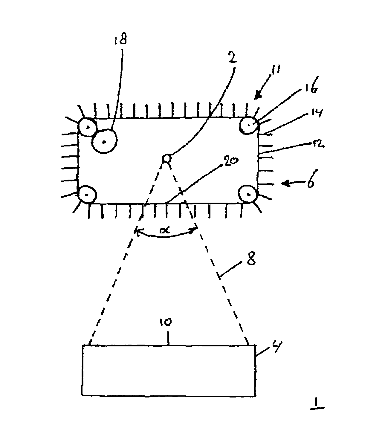
[0039]FIG. 2 shows an apparatus 1. The apparatus 1 includes a radiation source 2, a processing system 4, e.g. an illuminator IL, configured to process the radiation from the radiation source, and a filter system 6. The radiation source 2 may be a plasma radiation source, e.g. a Sn-source or a Xe-source. In the example of FIG. 2, the filter system 6 includes a transporter 11, which in this example includes a transport member 12, for example a conveyor belt, with a plurality of foils or plates 14, and a plurality of guides 16, for example wheels. In this example the conveyor belt 12 is configured as an endless loop. The wheels 16 are arranged to guide the conveyor belt 12. In this example the foils 14 are arranged orthogonal to the conveyor belt 12 and are spaced equidistantly with respect to each other. In the example of FIG. 2, the filter system further includes a drive unit 18. In this example the drive unit 18 is connected to a single wheel 16. The drive unit 18 drives conveyor be...

second embodiment

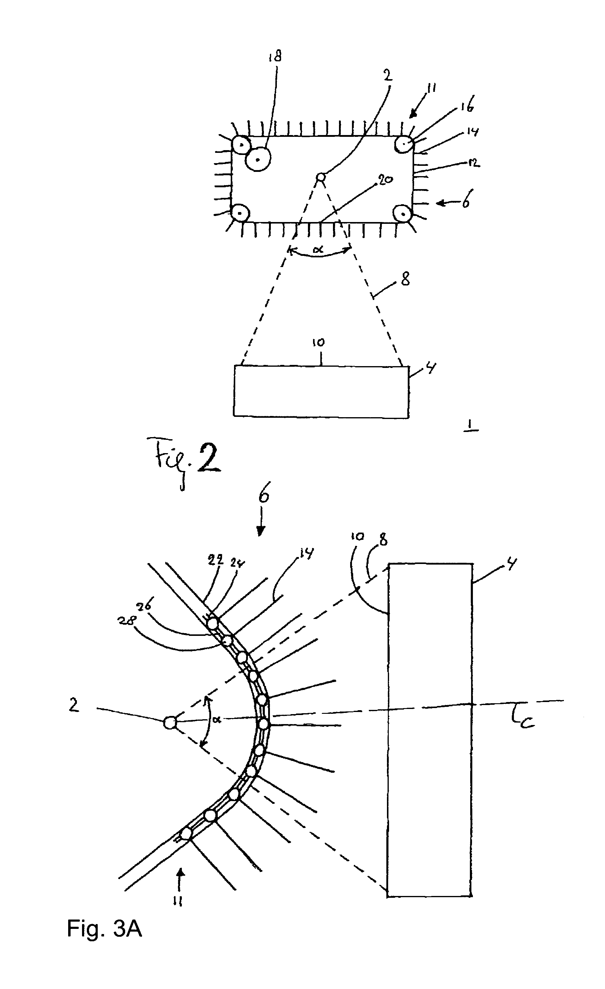
[0045]FIGS. 3a, 3b and 3c show the apparatus 1. FIG. 3a shows a schematic top view of an embodiment of the apparatus 1. FIG. 3b shows a schematic perspective view of a detail of the apparatus shown in FIG. 3a. FIG. 3c shows a schematic section of the apparatus shown in FIG. 3a along line C. Referring to FIG. 3a, the radiation source 2 generates radiation and debris particles, which, in this embodiment, are emitted radially away from the source 2. The radiation 8 propagating through the predetermined cross section 10, e.g. through the entrance opening of the processing system 4, has an opening angle α. In the embodiment of FIG. 3a each foil 14 substantially extends in a virtual plane that intersects the radiation source 2, at least within the radiation 8 through the predetermined cross section 10. The radiation 8 is parallel to the foils 14 within the radiation 8. In this way the foils 14 intercept a minimum amount of radiation from the radiation source 2. In the embodiment of FIG. 3...

third embodiment

[0050]FIGS. 4a and 4b show a schematic view of a third embodiment the apparatus 1. FIG. 4a shows the filter system 6 viewed from the location of the processing system. FIG. 4b shows the apparatus 1 as viewed in the direction of arrow P in FIG. 4a. In the embodiment of FIGS. 4a and 4b, the transporter 11 is configured to transport the foils or plates 14 on one side of a plane through the source 2 normal to the optical axis, which optical axis extends from the source 2 to the processing system 4. Thus, the transporter 11 can be arranged in front of the source 2, when viewed from the processing system 4, and need not be wrapped around the source. The positioning and mechanical layout of both the filter system 6 and the source 2 can thus be less constrained than with the transporter 11 wrapped around the source 2, or with rotating foils. In the embodiment of FIGS. 4a and 4b, the foils 14 are transported along the trajectory, which trajectory, within the radiation 8, substantially follow...


PUM


Abstract

Particles emitted by a radiation source, and moving from the radiation source towards a processing system for processing the radiation from the radiation source, are filtered out of radiation propagating through a predetermined cross section of the radiation as emitted by the radiation source by a filter system. The filter system includes a plurality of foils and a transporter for transporting the foils along a trajectory which extends within the beam so that the foils intercept the particles within the beam. The transporter is arranged to transport the foils by a substantially translatory movement of the foils along at least a part of the trajectory.

Description

BACKGROUND OF THE INVENTION[0001]1. Field of the Invention[0002]The present invention relates to a method for filtering particles out of a beam of radiation propagating from a radiation source towards a processing system, a filter system, an apparatus and a lithographic apparatus including the filter system.[0003]2. Description of the Related Art[0004]A lithographic apparatus is a machine that applies a desired pattern onto a substrate, usually onto a target portion of the substrate. A lithographic apparatus can be used, for example, in the manufacture of integrated circuits (ICs). In that instance, a patterning device, which is alternatively referred to as a mask or a reticle, may be used to generate a circuit pattern to be formed on an individual layer of the IC. This pattern can be transferred onto a target portion (e.g. including part of one or several dies) on a substrate (e.g. a silicon wafer). Transfer of the pattern is typically via imaging onto a layer of radiation-sensitiv...

Claims


Application Information

Patent Timeline
Patent Type & Authority Patents(United States)
IPC IPC(8): G21K3/00
CPCG03F7/70916
Inventor KLUNDER, DERK JAN WILFREDBAKKER, LEVINUS PIETERBANINE, VADIM YEVGENYEVICHVAN HERPEN, MAARTEN MARINUS JOHANNES WILHELMUS
Owner ASML NETHERLANDS BV
Why Eureka
Try Eureka