
System for mounting an underfloor electronic equipment

a technology for electronic equipment and mounting systems, which is applied in the field of rolling stock, can solve the problems of many steps in the conventional maintenance process, and achieve the effects of reducing the number of steps, reducing the cost, and reducing the operation tim

Inactive Publication Date: 2006-09-19
HITACHI LTD
View PDF4 Cites 3 Cited by
  • Summary
  • Abstract
  • Description
  • Claims
  • Application Information

AI Technical Summary

Benefits of technology

[0005]The object of the present invention is to reduce the number of steps related to mounting various electronic equipments to the rolling stock body and to reduce the cost related to manufacturing the body itself.
[0006]Another object of the present invention is to enable maintenance of the underfloor electronic equipment by accessing the equipment from only one side thereof, thus facilitating the replacement and maintenance of the electronic equipments (such as a power unit of an inverter) and cutting down operation time.

Problems solved by technology

The drawback of such electronic equipment mounting system is that various electronic equipment storage boxes exist in a scattered manner under the floor of the body, and at the time of maintenance of the electronic equipments, the operator must move back and forth between the outer side and the inner area of the body to disconnect the electrical connections between the electronic equipments stored in the storage box and the wiring provided to the body before removing the electronic equipments, and when necessary, the operator must remove the storage box storing the electronic equipments from the underfloor portion of the body.
Thus, the conventional maintenance process requires many steps.

Method used


Image

  • System for mounting an underfloor electronic equipment
  • System for mounting an underfloor electronic equipment
  • System for mounting an underfloor electronic equipment

Examples


Embodiment Construction

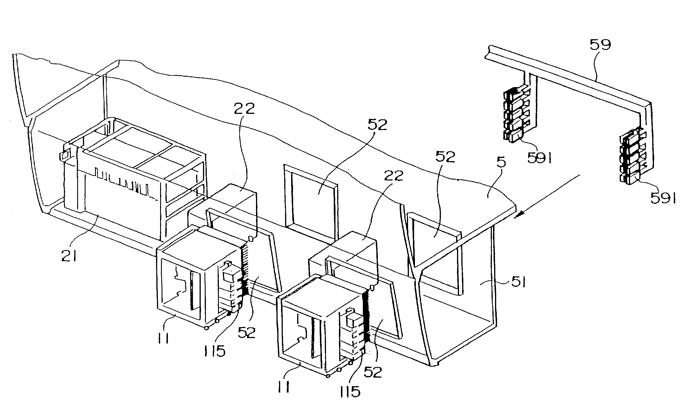
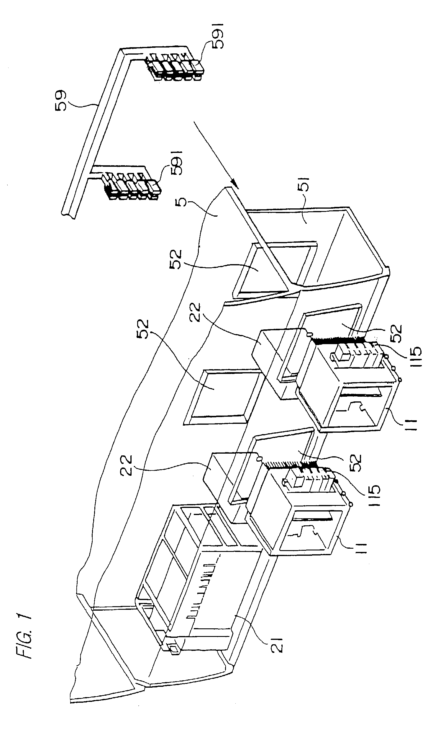
[0046]As shown in FIG. 1, the method for mounting an underfloor electronic equipment to a rolling stock body relates to a method for storing and fixing an underfloor electronic equipment such as a power unit 11 constituting an inverter device, a control unit 21 and a filter capacitor 22 to an underfloor storage portion 51 formed to the area under the floor of a rolling stock body 5.

[0047]The underfloor storage portion 51 is formed integrally with the body 5, positioned under the floor of the body along the longitudinal direction of the body. The function of the underfloor storage portion is to store in its inner space the underfloor electronic equipments, and to increase the rigidity of the body.

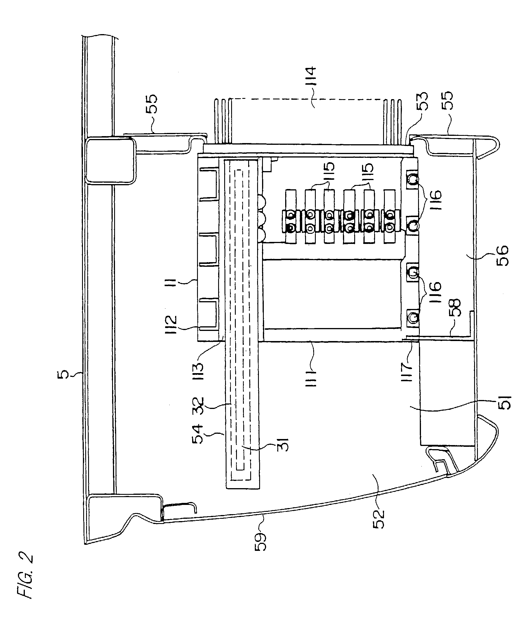
[0048]The underfloor storage portion 51 has on its outer-side surface an electronic equipment insertion opening 52 through which the electronic equipment passes, and further has a cooling opening 53 formed to the center-side surface through which a portion of the electronic equipment is expo...


PUM

PropertyMeasurementUnit
areaaaaaaaaaaa
rigidityaaaaaaaaaa
timeaaaaaaaaaa

Abstract

This invention relates to a system for mounting an underfloor electronic equipment to a rolling stock body having an underfloor storage portion formed under the floor in the longitudinal direction of the body as a portion of the body. The underfloor storage portion comprises a guidance tool for guiding and supporting the underfloor electronic equipment formed as a unit, a body-side connector corresponding to an electronic equipment-side connector formed to the electronic equipment, and a fixing tool for fixing the electronic equipment to the underfloor storage portion. The underfloor electronic equipment comprises a moving means guided by the guidance tool and the electronic equipment-side connector corresponding to the body-side connector. The electronic equipment can be moved by the guidance tool between a fixing position within the storage portion and a removal position outside the storage portion, the fixing tool used to fix the equipment to the fixing position where the equipment is electrically connected. The present invention facilitates maintenance and replacement of the electronic equipments and shortens operation time.

Description

FIELD OF THE INVENTION[0001]The present invention relates to a rolling stock (railcar), and more specifically, to a system for mounting underfloor electronic equipments to the rolling stock. It relates to a mounting system for providing under the floor of the rolling stock body a storage portion for storing underfloor electronic equipments, especially semiconductor devices such as inverter units and static inverter units, the storage portion formed integrally with the body.DESCRIPTION OF THE RELATED ART[0002]As shown in FIG. 6, according to a prior art system for mounting underfloor electronic equipments to a rolling stock, underfloor electronic equipments such as a power unit 11′ constituting an inverter unit, a control unit 21′, and an oil filter capacitor 22′ are stored and fixed to an electronic equipment storage box 9 which is mounted under the floor of a rolling stock body 5, and thereafter, the underfloor electronic equipments are connected with the wiring provided to the bod...

Claims


Application Information

Patent Timeline
Patent Type & Authority Patents(United States)
IPC IPC(8): B23P19/00B61D17/04B61C17/00H05K7/14
CPCB61C17/00H05K7/1427Y10T29/5313Y10T29/53165Y10T29/53213Y10T29/53174Y10T29/53252
Inventor TANAKA, TAKESHIMIZUGUCHI, NOBUAKITODORI, SEIJIROMITSUDOMI, SHINYAINA, YOSHIHIKONAKAIGAWA, SYU
Owner HITACHI LTD
Learn More