Flow control valve

a flow control and valve body technology, applied in the direction of fluid pressure control, process and machine control, instruments, etc., can solve the problems of corrosive gas generation, generated corrosive gas transmission through the diaphragm, etc., to achieve high yield, low manufacturing cost, and high durability

Inactive Publication Date: 2006-09-19
ASAHI YUKIZAI KOGYO CO LTD
View PDF16 Cites 30 Cited by
  • Summary
  • Abstract
  • Description
  • Claims
  • Application Information

AI Technical Summary

Benefits of technology

[0011]The present invention has been accomplished to solve the above problems of the prior art. It is an object of the present invention to provide a flow control valve characterized in that: it can be manufactured at a low manufacturing cost with a high yield; impurities are seldom dissolved out from the valve into the fluid so that the chemicals are seldom polluted; and the durability is high and the control performance is stable.

Problems solved by technology

However, the valve device, in which the above diaphragms are used, is disadvantageous in that gas is transmitted through the diaphragms.
Especially, in the case of a pipe line in which chemicals are used, corrosive gas is generated, by the chemicals, in some cases.
It is well known that the thus generated corrosive gas is transmitted through the diaphragms and metallic parts arranged close to the diaphragms are corroded.
However, PTFE is characterized in that the mechanical strength is low and, further, PTFE creeps easily.
Accordingly, when the rod made of PTFE is used over a long period of time, it is deformed or buckled, and the hydraulic control performance of the flow control valve is deteriorated.

Method used


Image

  • Flow control valve
  • Flow control valve
  • Flow control valve

Examples


Embodiment Construction

[0030]Referring to the accompanying drawings, an embodiment of the present invention will be explained below. Of course, the present invention is not limited to the specific embodiment.

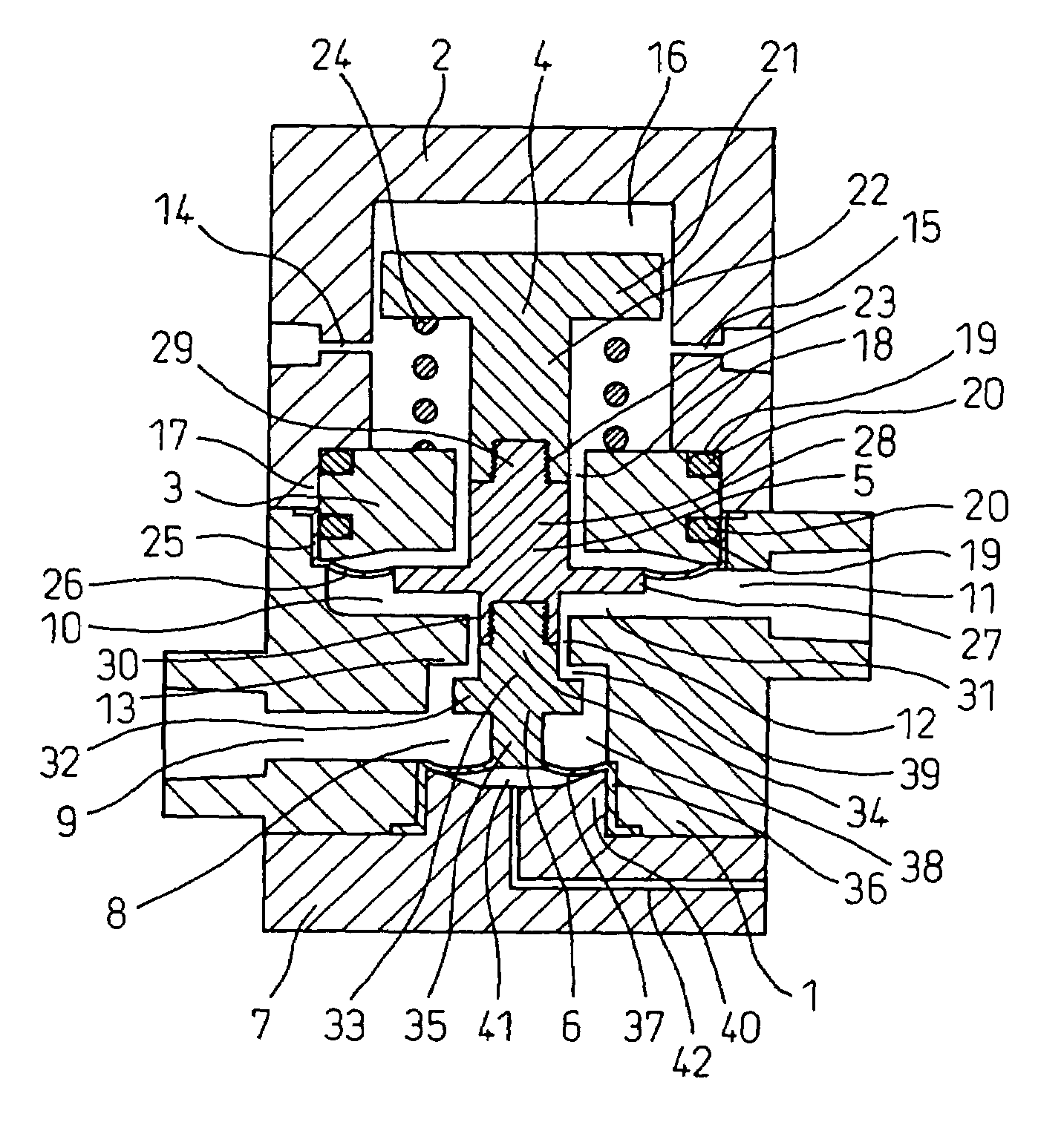
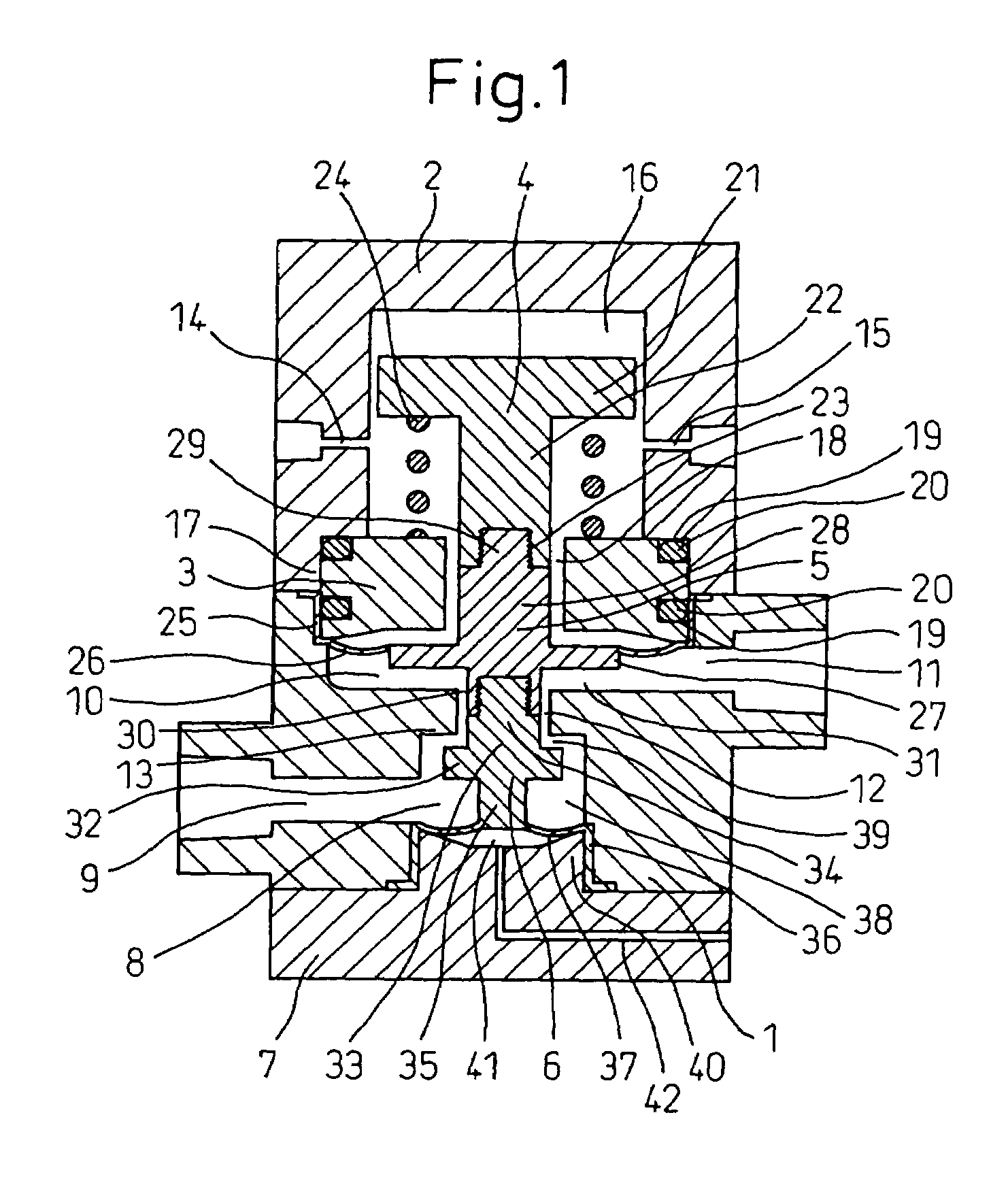
[0031]In the drawing, the main body 1 made of PTFE includes: a second cavity 8 which is provided being open to the bottom portion of the lower center; and a first cavity 10, the diameter of which is larger than that of the second cavity 8, the upper face of which is open to the upper portion. The main body 1 includes: an inlet passage 9 communicated with the second cavity 8, formed on the side of the main body 1; an outlet passage 11 communicated with the first cavity 10, formed on the face opposed to the inlet passage 9; and a communicating hole 12, the diameter of which is smaller than that of the first cavity 10, through which the first cavity 10 and the second cavity 8 communicate with each other. The valve seat 13 is formed on an upper face portion of the second cavity 8.

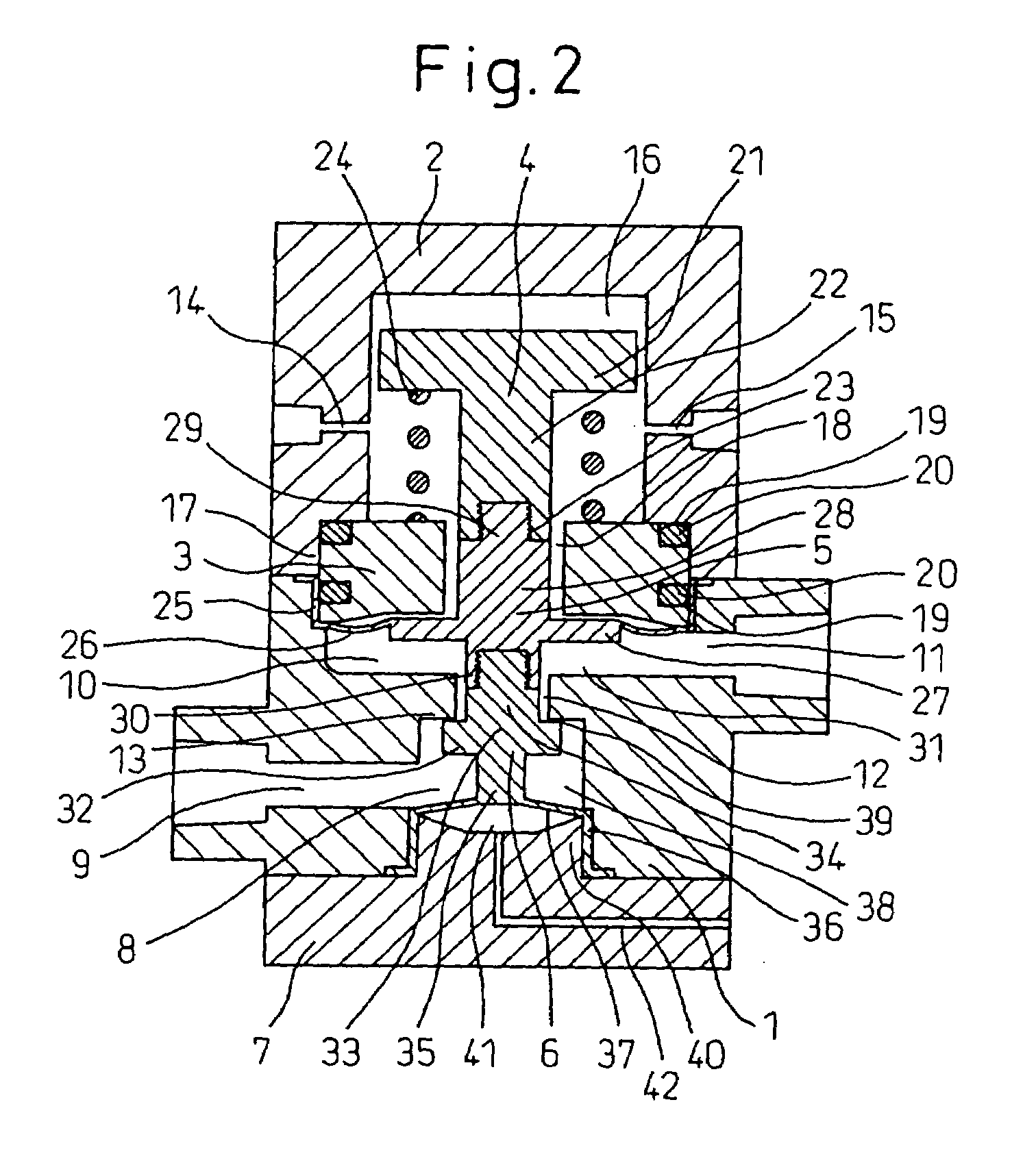
[0032]The bonnet 2 made o...


PUM


Abstract

A flow control valve includes a main body 1, bonnet 2, spring receiving portion 3, piston 4, spring 24, first diaphragm 27, first valve member 5, second valve member 6 and base plate 7, wherein an opening area of a hydraulic control portion composed of a valve element of the second valve member and a valve seat of the main body is changed according to a motion of the piston.

Description

FIELD OF THE INVENTION[0001]The present invention relates to a flow control valve used for a fluid transport pipe in which it is necessary to adjust a flow rate of the fluid transported in the pipe. More particularly, the present invention relates to a flow control valve, which is preferably used for an ultra demineralized water pipe line or various chemicals pipe lines in the semiconductor industry, capable of quickly responding to a change in the hydraulic pressure.BACKGROUND ART[0002]JP-A-6-295209 discloses a flow control valve.[0003]Referring to FIG. 5, the flow control valve disclosed in JP-A-6-295209 includes: a main body 53 having an inlet passage 51 and outlet passage 52; a valve portion 54; and a valve element 57 having a first diaphragm portion 55 and second diaphragm portion 56. By the first diaphragm portion 55 and second diaphragm portion 56, the chamber of the main body 53 is divided into a first pressure chamber 58 and a second pressure chamber 59. Constant pressure d...

Claims


Application Information

Patent Timeline
Patent Type & Authority Patents(United States)
IPC IPC(8): F16K31/145F16K31/122F16K31/126F16K41/12G05D7/01G05D16/06
CPCF16K31/1221G05D16/0652G05D16/0647F16K41/12G05D7/01F16K31/122F16K31/126
Inventor YOSHINO, KENROHAGIHARA, SHUNICHIRO
Owner ASAHI YUKIZAI KOGYO CO LTD
Why Eureka
Try Eureka