

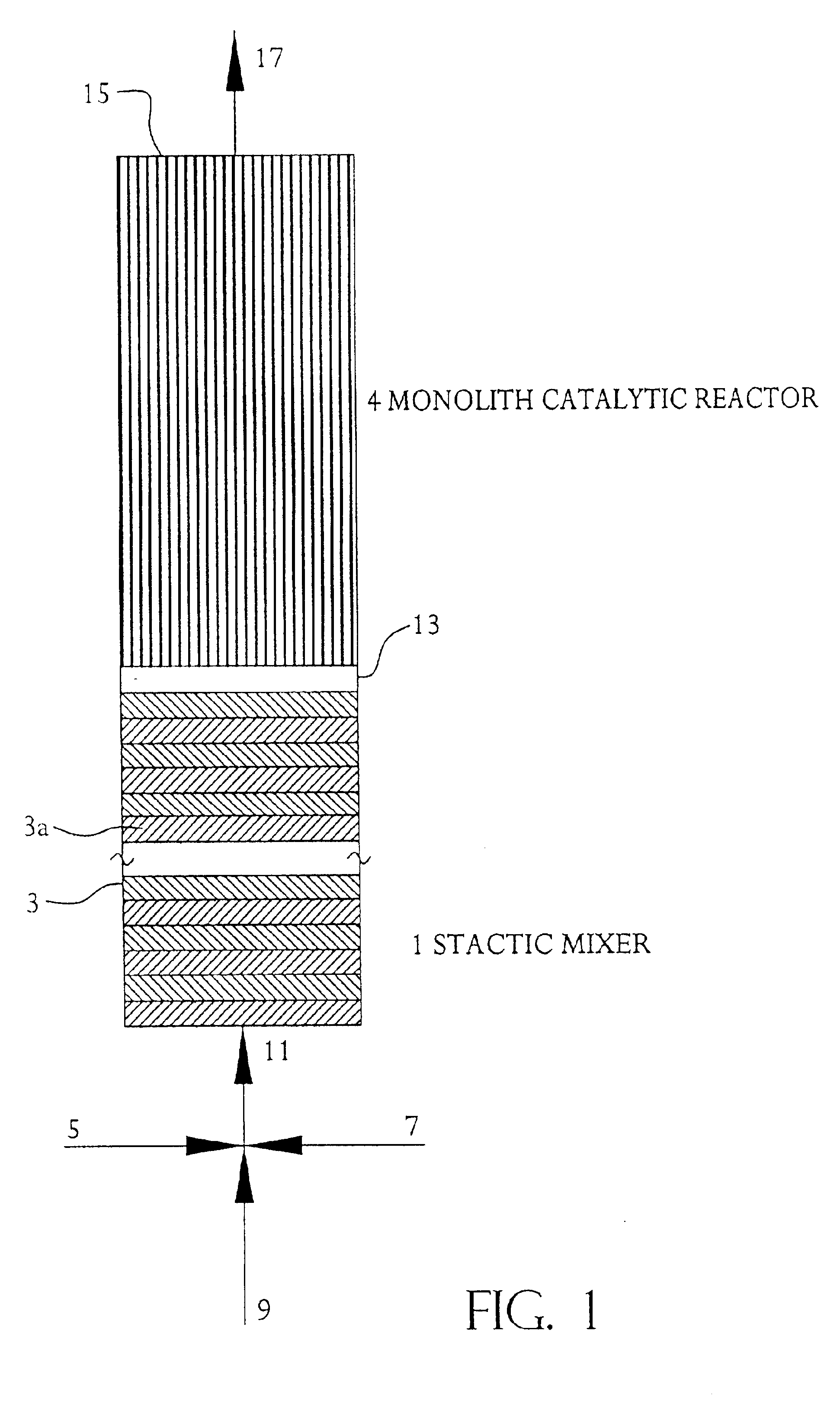
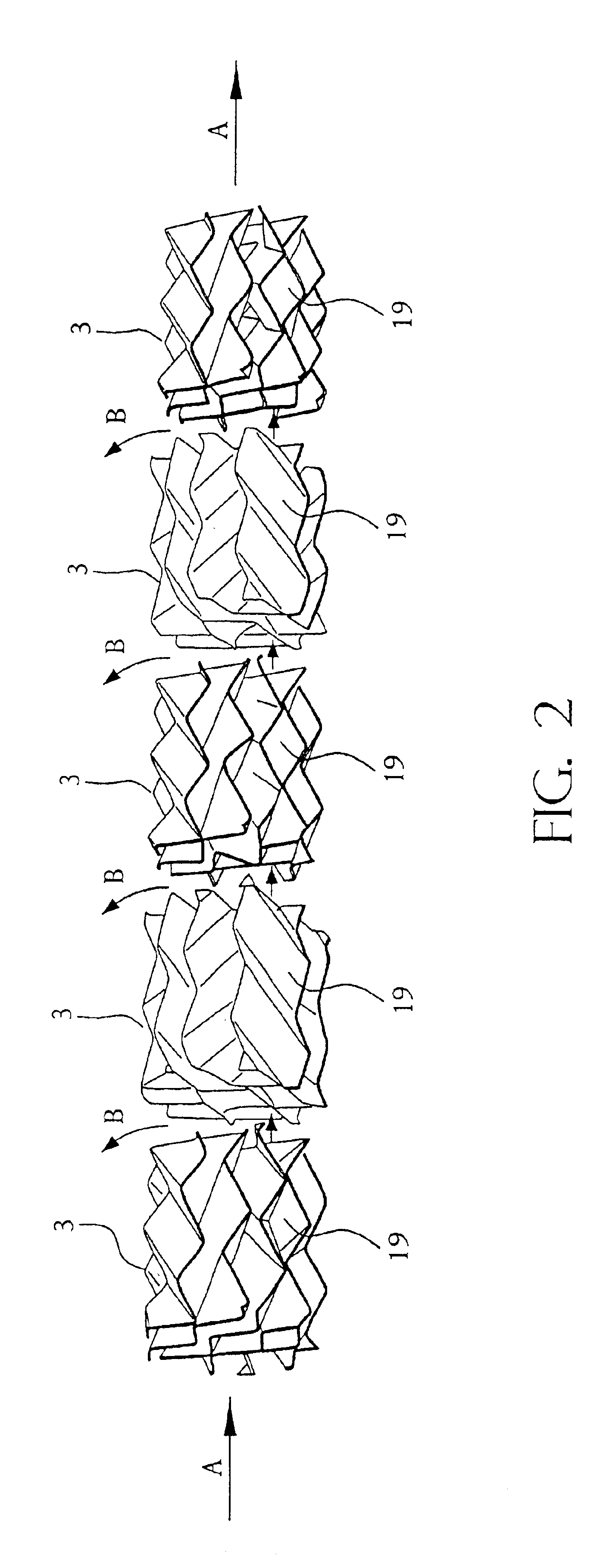
Monolith catalytic reactor coupled to static mixer
a technology mixer, which is applied in the direction of liquid-gas reaction of thin-film type, physical/chemical process catalyst, gas-gas reaction process, etc., can solve the problems of insufficient operation and productivity, inherently problematic slurry phase reaction system in chemical process safety, operability and productivity, and shorten the catalyst life. , to achieve the effect of enhancing throughput and efficiency of monolith catalytic reactor
- Summary
- Abstract
- Description
- Claims
- Application Information
AI Technical Summary
Benefits of technology
Problems solved by technology
Method used
Image

Examples
example 1
Hydrogenation of Dinitrotoluene in System Comprised of Static Mixer and Monolith Catalytic Reactor
[0042]In carrying out the hydrogenation of dinitrotoluene, a reactor comprised of a cylindrical monolith reactor bed, approximately 100″ high and 1″ in diameter is used. The catalyst bed is made from a commercial 400 cells per square inch (cpi) cordierite monolith support having square shaped cells with a 25% alumina washcoat and a catalyst metal loading of 20% Ni and 1% Pd based on the washcoat. The reactor system is set up similar to FIG. 1 with the excess hydrogen gas being recycled to the inlet of the reactor using a compressor.
[0043]Hydrogen is fed in excess of the stoichiometric requirement for dinitrotoluene hydrogenation. The dinitrotoluene is continuously fed as a molten liquid and no solvent is employed. Both the dinitrotoluene feed and the recycled hydrogen are fed into the recycled reaction mixture at the entrance to the static mixer at a mixing “cross.”
[0044]In this demonst...
PUM
| Property | Measurement | Unit |
|---|---|---|
| superficial velocity | aaaaa | aaaaa |
| angles | aaaaa | aaaaa |
| angle | aaaaa | aaaaa |
Abstract
Description
Claims
Application Information