Precision relaxation oscillator without comparator delay errors

a relaxation oscillator and delay error technology, applied in the field of improved oscillator circuits, can solve the problems of increasing supply current requirements, affecting the implementation and quality of the resulting periodic output signal waveform, and compromising the accuracy at high speed of operation

Active Publication Date: 2006-09-19
MAXIM INTEGRATED PROD INC
View PDF4 Cites 28 Cited by
  • Summary
  • Abstract
  • Description
  • Claims
  • Application Information

AI Technical Summary

Problems solved by technology

However, conventional relaxation oscillators suffer from a number of limitations that affect both their implementation and the quality of the resulting periodic output signal waveform.
This usually has the side effect of increased supply current requirements and compromised accuracy at high speeds of operation.

Method used


Image

  • Precision relaxation oscillator without comparator delay errors
  • Precision relaxation oscillator without comparator delay errors
  • Precision relaxation oscillator without comparator delay errors

Examples


Embodiment Construction

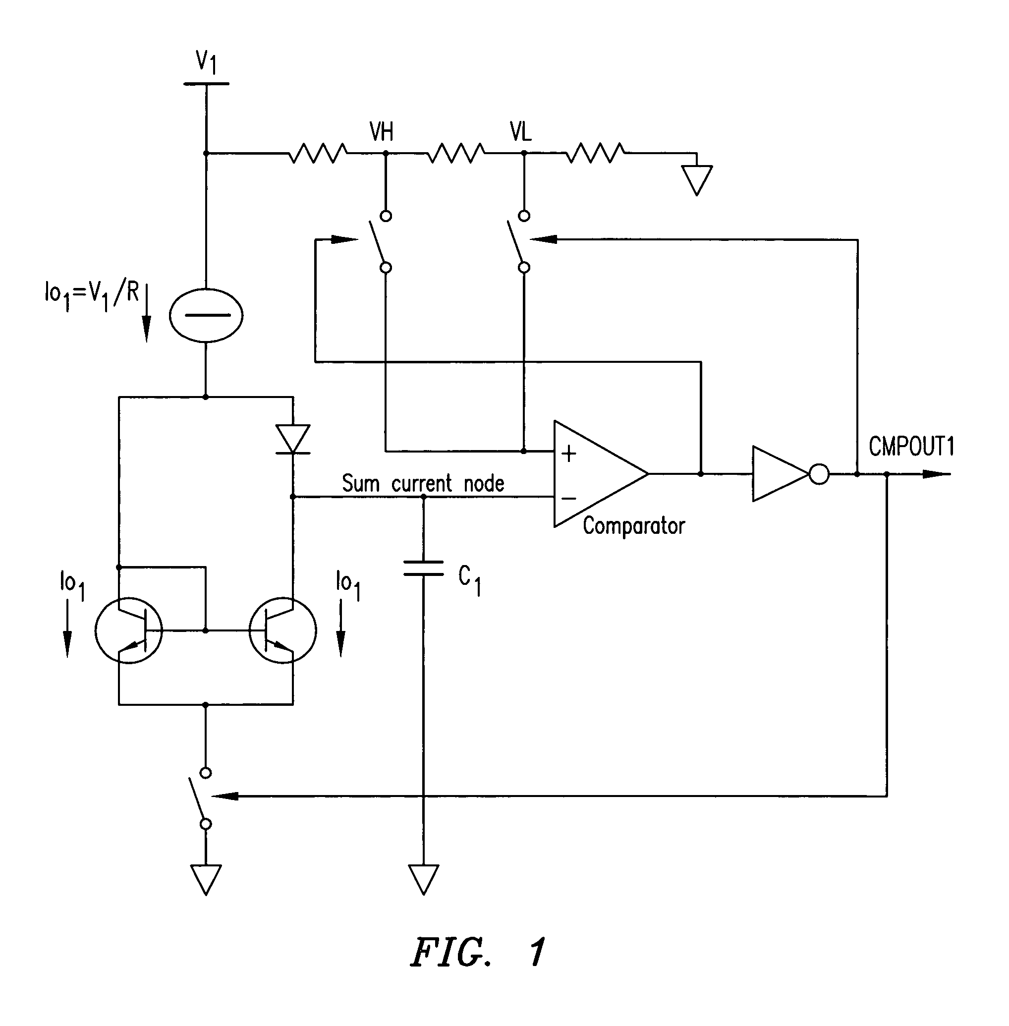
[0021]Reference is now made to the Drawings wherein like reference characters denote like or similar parts throughout the various Figures. Referring now to FIG. 1, a conventional relaxation oscillator is illustrated. The conventional relaxation oscillator illustrated in FIG. 1 is comprised primarily of voltage to current generation circuitry producing a current Io1 from an input voltage V1 that is supplied to a sum current node, a timing capacitor C1 connected between the sum current node and ground, a comparator having an input connected to the sum current node, and an inverter connected to an output of the comparator.

[0022]The conventional relaxation oscillator operates by alternately charging and discharging the timing capacitor C, between two internally set switching threshold voltage levels VH and VL to generate a period waveform as an input into the comparator. This results in the generation of a periodic output signal waveform CMPOUT1 whose frequency is inversely proportional...


PUM


Abstract

A relaxation oscillator for generating an oscillator output signal having a predetermined frequency. The relaxation oscillator includes an interleaved charge pump for providing a restoring charge to an integrator in response to at least one charge pump control signal. The relaxation oscillator further includes an integrator having an integrator input connected to the current summing node. The integrator is adapted to produce an integrator output signal having the predetermined frequency at an integrator output. A comparator having an input connected to the integrator output is adapted to generate the oscillator output signal having the predetermined frequency in response to the integrator output signal.

Description

TECHNICAL FIELD OF THE INVENTION[0001]The present invention relates to an improved oscillator circuit, and in particular to an improved relaxation oscillator without comparator delay errors.BACKGROUND OF THE INVENTION[0002]A variety of methods are known for creating oscillator circuits for providing periodic signals of a desired frequency. A large class of oscillator configurations that exist in monolithic integrated circuit design are those known as relaxation oscillators or multivibrators. Conventional relaxation oscillators operate by alternately charging and discharging a timing capacitor between two internally set threshold voltage levels. This results in the generation of a periodic output signal waveform whose frequency is inversely proportional to the value of the timing capacitor. Conventional relaxation oscillator configurations include R-C charge and discharge oscillators, constant-current charge and discharge oscillators, and emitter-coupled multivibrators.[0003]However,...

Claims


Application Information

Patent Timeline
Patent Type & Authority Patents(United States)
IPC IPC(8): H03L7/00H03B5/10H03K4/502
CPCH03K4/502
Inventor MADER, URS H.KO, YVONNECOCETTA, FRANCOKOTOWSKI, JEFFYU, XIAOYING
Owner MAXIM INTEGRATED PROD INC
Why Eureka
Try Eureka