Light modulation apparatus, image pickup apparatus, and drive methods therefor

a technology of light modulation apparatus and pickup apparatus, which is applied in the direction of optics, instruments, static indicating devices, etc., can solve the problems of difficult to put into practical use a light modulation apparatus using a liquid crystal cell, light modulation apparatuses using no polarizing plates, and related art light modulation apparatus shown in the figures. , to achieve the effect of enhancing contrast ratio, improving transmittance, and keeping constant light quantity

Inactive Publication Date: 2006-09-19
SONY CORP
View PDF18 Cites 11 Cited by
  • Summary
  • Abstract
  • Description
  • Claims
  • Application Information

AI Technical Summary

Benefits of technology

[0017]A first object of the present invention is to provide a light modulation apparatus capable of i

Problems solved by technology

The related art light modulation apparatus shown in the figures has a problem.
This problem is one of factors which make it difficult to put a light modulation apparatus using a liquid crystal cell into practical use.
These light modulation apparatuses using no polarizing plate have a problem.
The light modulation apparatus of the high polymer scattering type has another problem in significantly degrading, when the apparatus is used for an image pickup apparatus, the image formation performance of an optical system of the image pickup apparatus.
The related art light modulation apparatus presents a further problem.
The related art light modulation apparatus has the following problem associated with the drive thereof.
To drive the related art light modulation apparatus, the transmittance has been controlled by modulating a magnitude of a DC voltage or AC voltage applied to the apparatus; however, for the light modulation apparatus at a consumer level, it is difficult to accurately perform voltage control and to obtain a characteristic having a low threshold value; a limitation lies in the number of gradation of the transmittance level; and D/A conversion is

Method used


Image

  • Light modulation apparatus, image pickup apparatus, and drive methods therefor
  • Light modulation apparatus, image pickup apparatus, and drive methods therefor
  • Light modulation apparatus, image pickup apparatus, and drive methods therefor

Examples


first embodiment

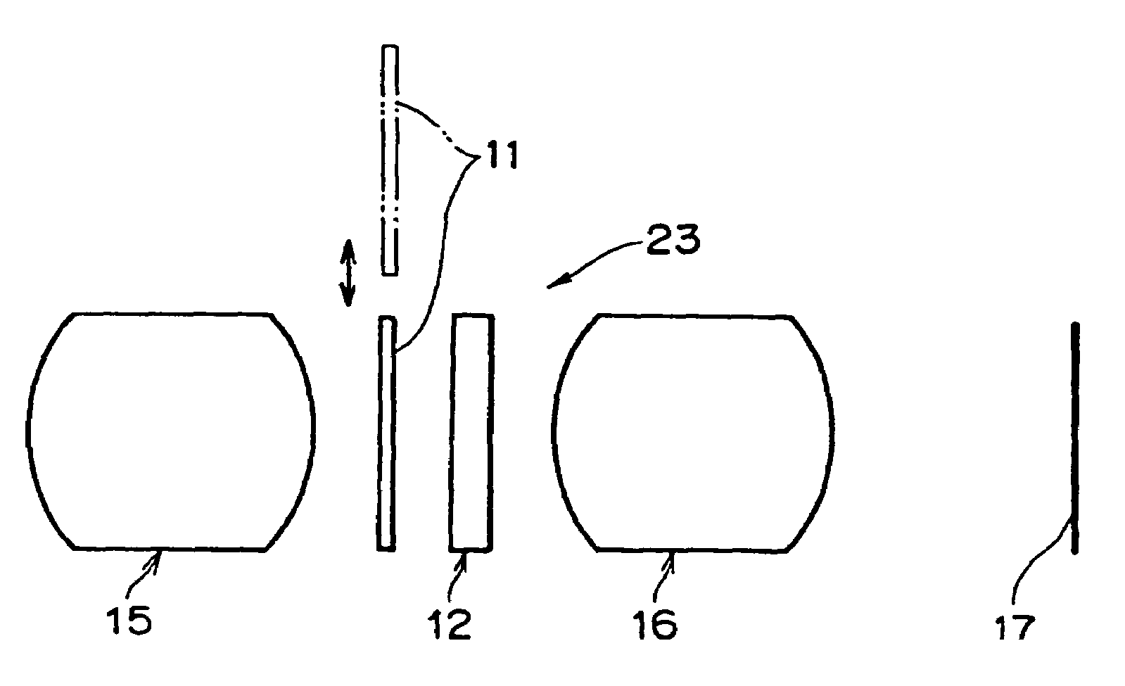
[0092]Referring to FIGS. 3A to 3C, there is shown a light modulation apparatus according to a first embodiment of the present invention, which apparatus includes a guest-host type liquid crystal cell (GH cell) 12 containing a host material 13 and a guest material 4, and a polarizing plate 11 disposed on the incident side of the GH cell 12.

[0093]A negative type liquid crystal having a negative dielectric constant anisotropy (Δ∈), produced by Merck under a trade name of MLC-6608, was used as the host material 13. A positive type dichroic dye having a positive light absorption anisotropy (ΔA), produced by BDH under a trade name of D5, was used as the guest material 4.

[0094]With respect to the light modulation apparatus configured as described above, a change in transmittance (expressed in percentage based on the total quantity of light perfectly passing through the liquid crystal cell and the polarizing plate) of the light modulation apparatus was measured in air by applying an operati...

second embodiment

[0126]In this embodiment, a response speed of a light modulation apparatus upon application of a voltage thereto was examined.

[0127]The response speed of a light modulation apparatus upon application of a voltage thereto varies depending on not only the kind of drive of the apparatus but also means used for producing a liquid crystal device, for example, a rubbing process. The rubbing process involves forming a film made from a high polymer such as polyimide or polyvinyl alcohol on a substrate, and rubbing the film with cloth, thereby uniformly aligning liquid crystal molecules in the rubbing direction [D. W. Berrenan, Mol. Cryst. & Liq. Cryst., 23.215(1973)].

[0128]Examples of the rubbing processes include a parallel rubbing process, an anti-parallel rubbing process, and a one-side rubbing process. The parallel rubbing process shown in FIG. 5A involves rubbing both alignment films formed on upper and lower substrates in such a manner that the rubbing direction on the upper alignment...

third embodiment

[0149]In this embodiment, the control of a transmittance of a light modulation apparatus by modulating a pulse width or a pulse density of drive pulses applied to a GH cell of the apparatus was examined.

[0150]In particular, the modulation of a pulse width of each drive pulse for controlling a transmittance of the light modulation apparatus is effective to independently perform the control of the transmittance and the compensation of the transmittance. Specifically, the transmittance is normally controlled by modulating the pulse width of each drive pulse on the basis of a normal feedback control signal and the transmittance is compensated by modulating the pulse height of the drive pulse on the basis of a temperature correction feedback signal, or the transmittance is normally controlled by modulating the pulse height of each drive pulse on the basis of a normal feedback control signal and the transmittance is compensated by modulating the pulse width of the drive pulse on the basis...


PUM


Abstract

Disclosed are a light modulation apparatus including a liquid crystal device; and a polarizing plate disposed in an optical path of light made incident on said liquid crystal device; wherein said liquid crystal device is of a guest-host type using a negative type liquid crystal as a host material, an image pickup apparatus using the light modulation apparatus, and methods of driving the light modulation apparatus and image pickup apparatus.

Description

[0001]The present application is a divisional of U.S. patent application Ser. No. 09 / 711,651 filed Nov. 13, 2000 now U.S. Pat. No. 6,804,037, which claims priority to Japanese Application Nos. P11-322184 filed Nov. 12, 1999, P11-322185 filed Nov. 12, 1999, P11-322186 filed Nov. 12, 1999, P11-322187 filed Nov. 12, 1999 and P2000-319879 filed Oct. 19, 2000, all of which are hereby incorporated by reference to the extent permitted by law.BACKGROUND OF THE INVENTION[0002]The present invention relates to a light modulation apparatus for modulating the quantity of incident light and outputting the modulated light and an image pickup apparatus using the light modulation apparatus, and methods of driving the light modulation apparatus and the image pickup apparatus.[0003]Light modulation apparatuses have been known of a type including a liquid crustal cell, typically, a twisted nematic (TN) type liquid crystal cell or a guest host type liquid crystal cell (GH cell), and a polarizing plate.[...

Claims


Application Information

Patent Timeline
IPC IPC(8): G02F1/07G09G3/36G02F1/137G02F1/133G02F1/139
CPCG02F1/13318G02F1/133528G02F1/13725G09G2320/041G02F2001/13312G02F2001/13712G02F1/13312G02F1/13712G02F1/137
Inventor NITO, KEIICHIUDAKA, TORU
Owner SONY CORP
Why Eureka
Try Eureka