[0017]It is an object of the invention to provide a method, a radio transmission unit, a module for a radio transmission unit and a radio communications network comprising such a radio transmission unit which enable a simple determination of separate radio frequency gains for different carriers in a multi-carrier transmitter of a radio transmission unit of a radio
communications system.
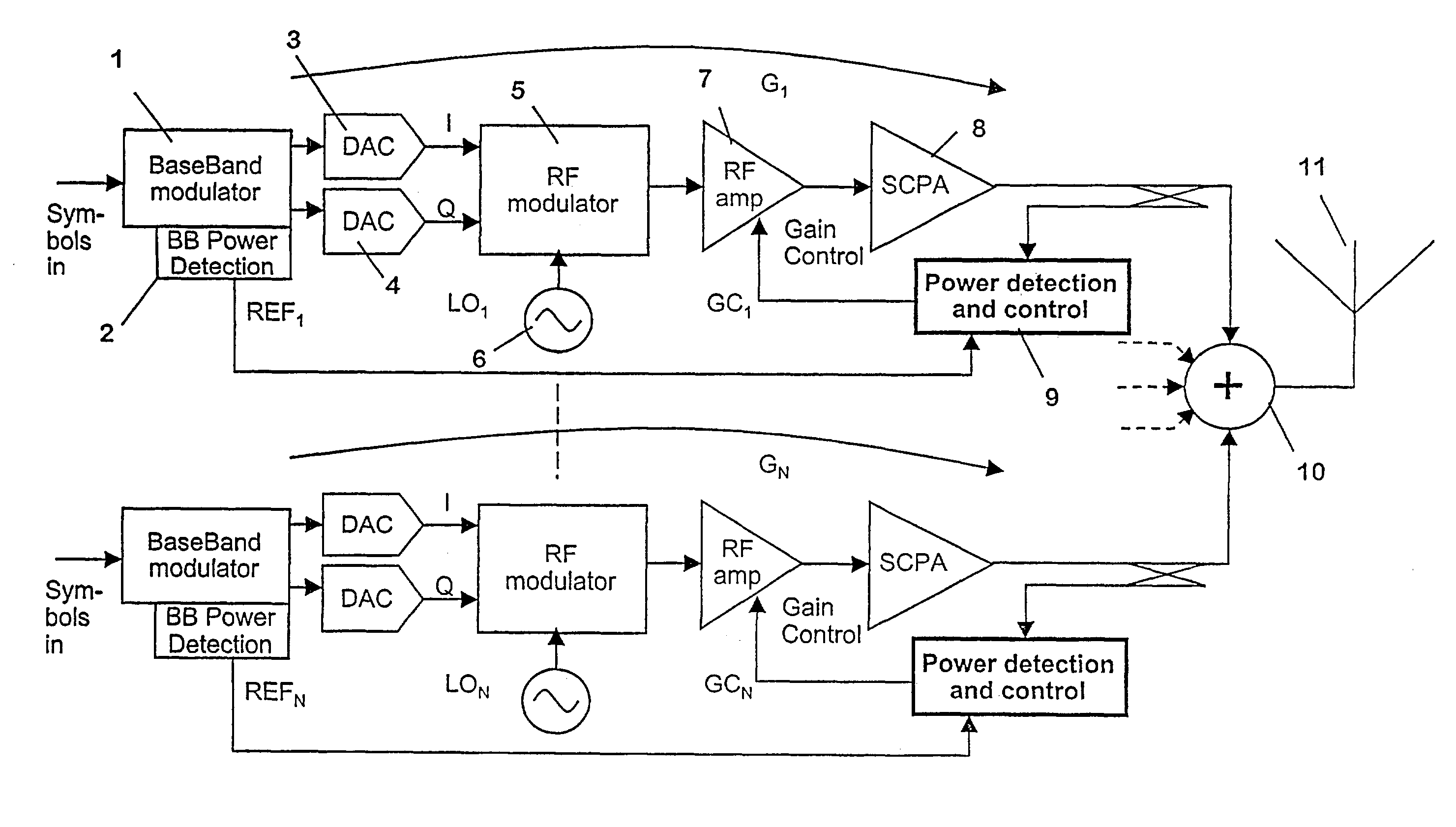
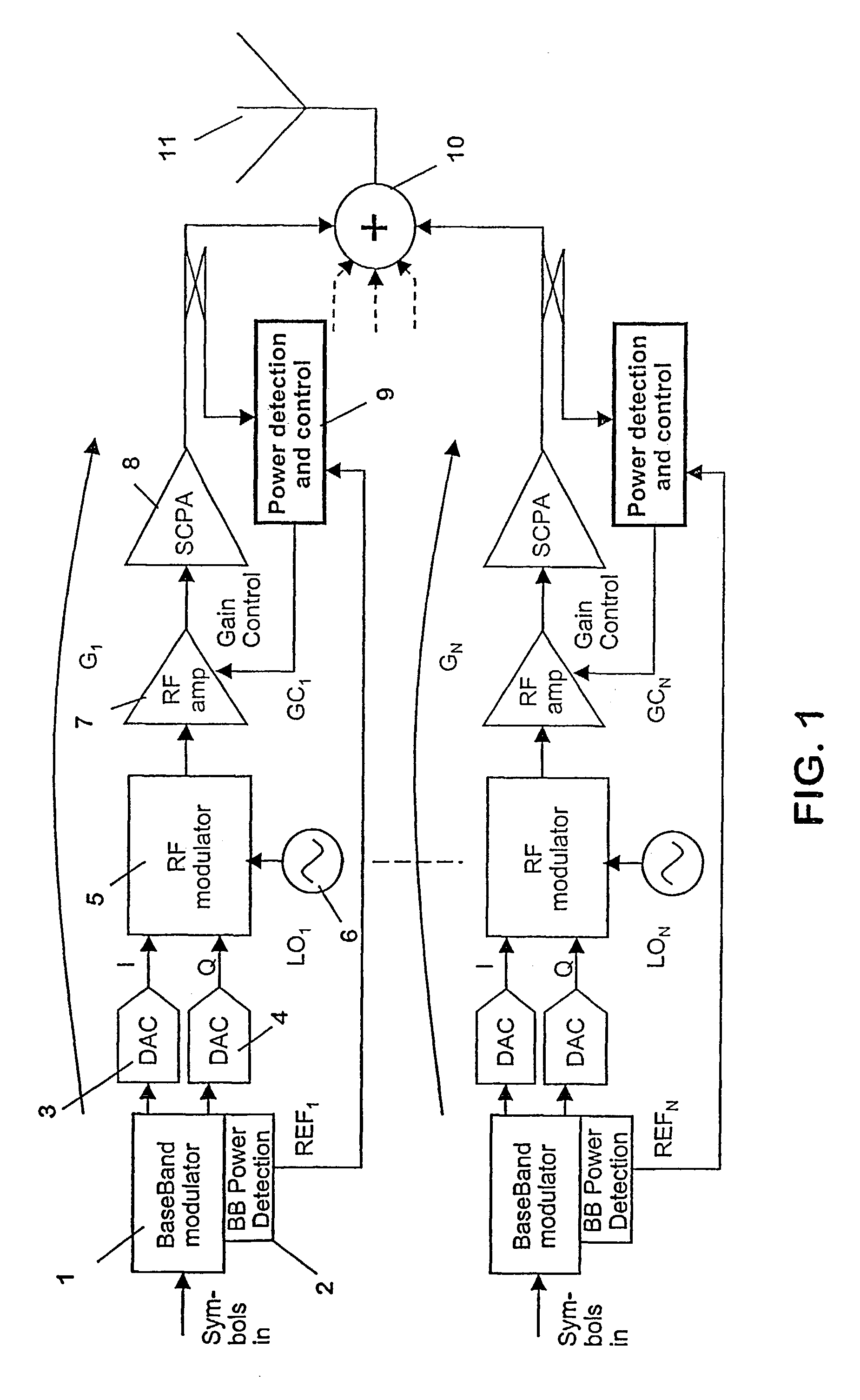
[0025]The methods, the radio transmission units and the modules of the first alternative of the invention proceed from the idea that the total power of the summed carriers output by the multi-carrier power
amplifier can be described mathematically with the powers of predetermined signals in the single carrier units as variable but known coefficients and the total RF
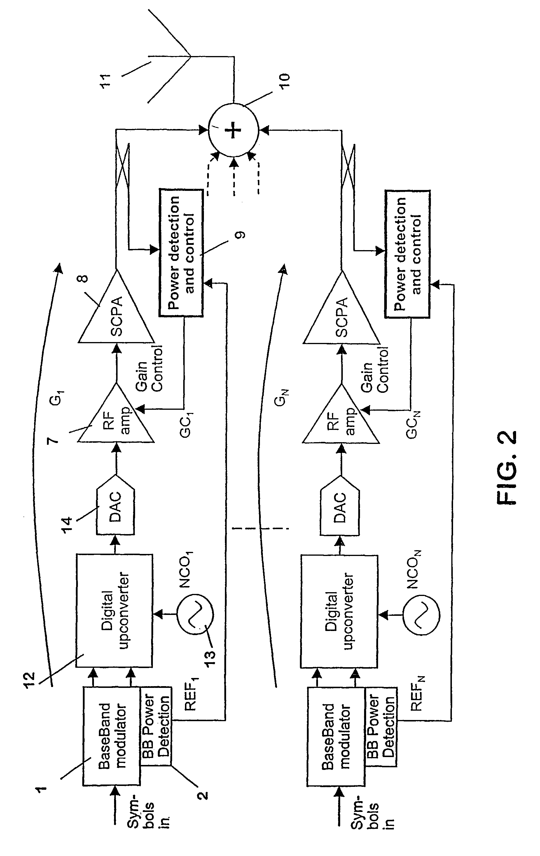
gain for each carrier as unknown values. The predetermined signals can be either signals input to the means for modulating the different carriers, or signals input to digital-to-analogue
converters included in the single carrier units. The powers of the signals in the single carrier units can be determined easily and each variation in these powers leads to a corresponding variation in the total output power. A plurality of sets of different powers of the signals input to the means for modulating or to the digital-to-analogue
converters respectively and the corresponding total output power deliver a plurality of equations that can be solved mathematically in case at least as many sets are supplied as carriers are present. The proposed methods, radio transmission units and modules according to the first aspect of the invention therefore enable to determine the gains of the individual carriers without using a channeliser, but nevertheless accurately. Avoiding channelisers means that the implementation can be simpler and there are less problems in frequency hopping.
[0033]According to the second proposed alternative of the invention, in contrast, the single-carrier powers are determined before summing of the modulated carriers to a multi-carrier
signal, but only used relatively to each other. Even though it is not possible to determine the powers of the modulated carriers input to the multi-carrier power amplifier accurately, it is possible to mutually track the powers accurately. This makes it possible to compare the relative strengths of the individual carrier powers at the output of the low-power part of the multi-carrier transmitter. The determined relative strengths can then be used to distribute the total power or the total
gain determined for the summed carriers to the individual carriers. The gains for the different carriers in the multi-carrier power amplifier can be taken into account for this distribution. Thus, an accurate individual gain value for each carrier can be obtained.
[0034]The second proposed alternative of the invention has several advantages compared to the first proposed alternative. There is no need to solve a
system of equations and the gain information can be obtained directly after a
single measurement, so there is no need to wait for a series of measurements. Possibly, even less accuracy is needed in the measurement of the multi-carrier
signal. Finally, the second alternative of the invention is also suited for fixed carrier powers. The
advantage of the first proposed alternative, in contrast, is that less RF power detectors are needed. Moreover, in the second alternative, the
frequency response of the
MCPA, apart from a constant, has to be known reliably a priory.
[0035]Both alternatives according to the invention use mathematical evaluations of determined powers in order to allow for a simple and accurate determination of the individual RF gain of different carriers in a multi-carrier radio transmission unit.
[0040]In most radio transmission units, the power of the signals provided for RF modulation can be varied in time slots in order to adapt the
transmitted power to the needs of the mobile. More specifically, in TDMA systems, the power of each carrier can be varied in time slots. In
CDMA systems, in contrast, the power of the user codes can be varied in user
specific time slots, the time slots of different users not being synchronised to each other and each carrier serving a plurality of users. Accordingly, in the carrier power of a
CDMA signal, the time slots cannot be recognised any more. The possibility of varying the transmission power reduces the interference within the network and to other networks.

